


‑125‑
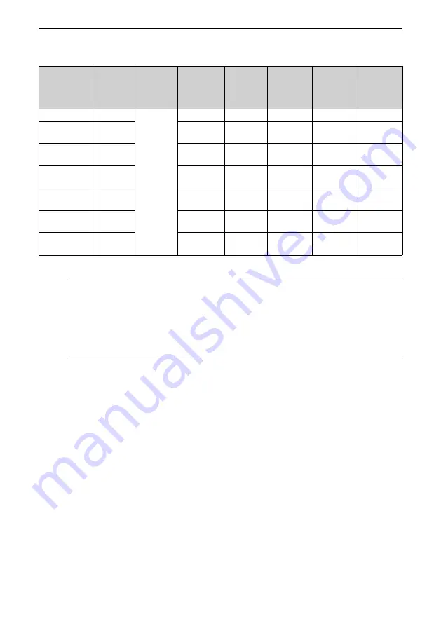
Table 3–32 Brake specifications
Motor Model
Holding
Torque
(N·m)
Supply
Voltage
(VDC)
±10%
Coil Resistance
(Ω)±7%
Exciting
Current
(A)
Release Time
(ms)
Apply Time
(ms)
Backlash
(°)
MS1H1‑05B/10B
0.32
24
94.4
0.25
≤ 20
≤ 40
≤ 1.5
MS1H1‑20B/40B
MS1H4‑40B
1.5
75.79
0.32
≤ 20
≤ 60
≤ 1.5
MS1H1‑75B/
MS1H4‑75B
3.2
57.6
0.42
≤ 40
≤ 60
≤ 1
MS1H2‑10C/15C/
20C/25C
8
25
0.96
≤ 30
≤ 85
≤ 0.5
MS1H2‑30C/40C/
50C
16
21.3
1.13
≤ 60
≤ 100
≤ 0.5
MS1H3‑85B/13C/
18C
12
29.7
0.81
≤ 60
≤ 120
≤ 0.5
MS1H3‑29C/44C/
55C/75C
50
14.4
1.67
≤ 100
≤ 200
≤ 0.5
Note
●
The brake cannot share the same power supply with other electrical devices. This
is to prevent malfunction of the brake due to voltage or current drop caused by
other working devices.
●
It is recommended to use cables with a cross‑sectional area of 0.5 mm
2
and above.
Summary of Contents for SV660P Series
Page 1: ...SV660P Series Servo Drive Hardware Guide Data code 19011391 A00...
Page 55: ...Installation 54 Figure 2 21 Installing the ferrite clamp...
Page 111: ...Wiring 110 Open collector mode For use of the internal 24 V power supply of the servo drive...
Page 113: ...Wiring 112 Scheme 2 Using the external resistor...
Page 144: ...Maintenance 143...


