


‑
108
‑
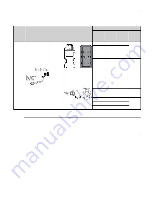
Table 3–29 Absolute encoder cable connector (MIL‑DTL‑5015 series 3108E20‑29S aviation
connector)
Applicable
Motor
Flange Size
[1]
Outline Drawing of the Connector
Terminal Pin Layout
Pin No.
Signal
Name
Color
Type
100
130
180
Servo drive
side
6‑pin male (The joint face
is on the right side.)
1
+5V
Red
Twisted
pair
2
GND
Orange
5
PS+
Blue
Twisted
pair
6
PS‑
Purple
Enclosure
PE
‑
‑
Motor Side
A
PS+
Yellow
Twisted
pair
B
PS‑
Yellow‑
black
E
Battery (+)
Blue
‑
F
Battery (‑) Blue‑black
G
+5V
Red
‑
H
GND
Black
J
Shield
‑
Note
[1] The flange size refers to the width of the mounting flange.
3.8
Connecting the Control Signal (CN1)
Observe the requirements in standard EN 60204‑1 during connecting control circuit
cables.
3.8.1 Wiring of I/O Signal Cables
I/O signal cable selection
It is recommended to use shielded signal cables to prevent I/O signal circuit from
being disturbed by external noise. Use separate shielded cables for different analog
signals. It is recommended to use shielded twisted pairs for digital signals.
Summary of Contents for SV660P Series
Page 1: ...SV660P Series Servo Drive Hardware Guide Data code 19011391 A00...
Page 55: ...Installation 54 Figure 2 21 Installing the ferrite clamp...
Page 111: ...Wiring 110 Open collector mode For use of the internal 24 V power supply of the servo drive...
Page 113: ...Wiring 112 Scheme 2 Using the external resistor...
Page 144: ...Maintenance 143...


