80448418 Rev.C
1
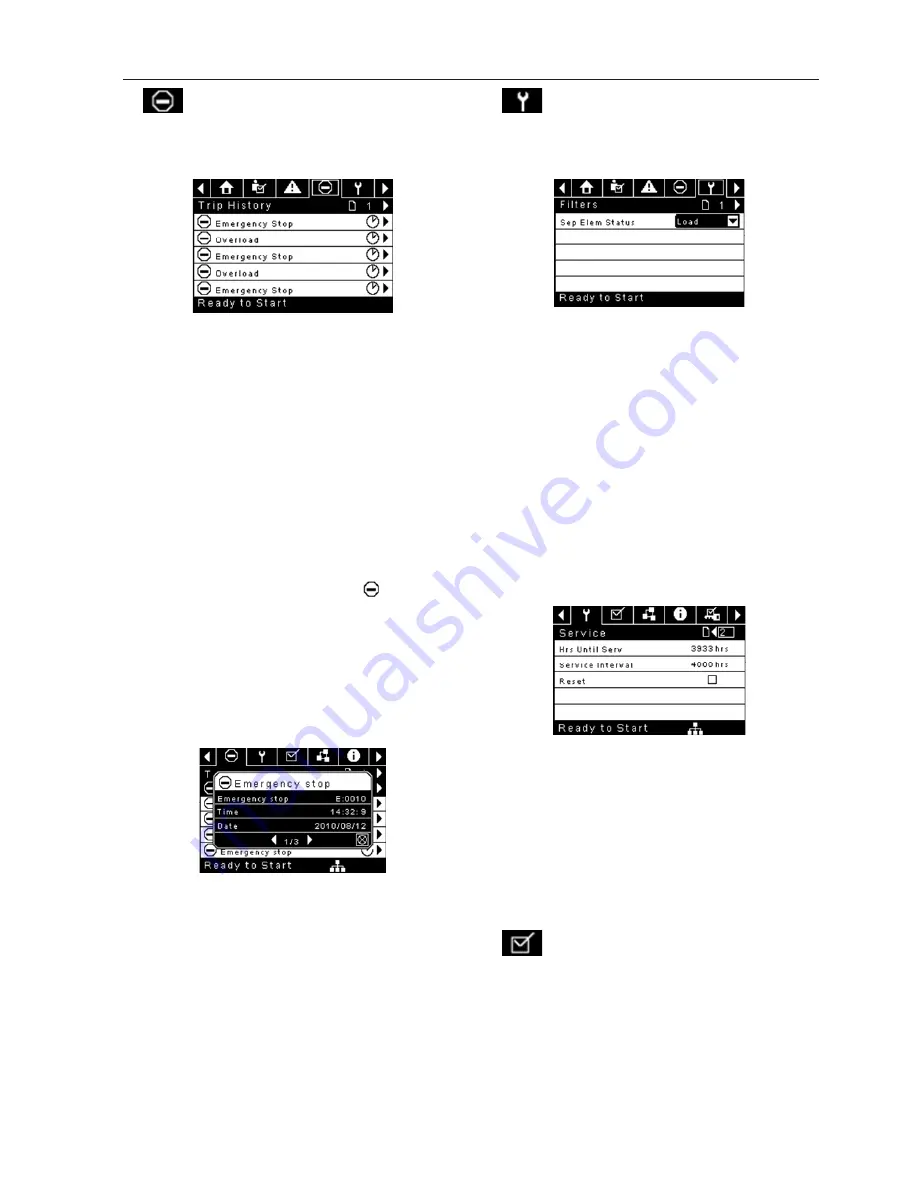
TRIP HISTORY
Pages 1 to a Max of 3
Figure 13 : Trip History
The pages in the Trips History folder document up to the
last 15 trips that the controller has experienced, and time
stamps each�� The trips are recorded in sequence, with
number one being the newest and 15 being the oldest��
When a new trip occurs, it becomes number one and all
others are shifted up in number��
The page numbers in the Title Bar are used to scroll
through the events, with each page displaying up to
seven�� Page one displays events one through five, page
two displays six through ten, and so on��
The following items will generate an entry in the trip
history��
Trips
Active Trips will show a flashing trip icon
while
acknowledged Trips will have a solid icon��
The trip history also records compressor data at the time
of the trip to assist in diagnostics and troubleshooting��
Navigating to the trip entry and hitting the right
navigation button will bring up the trip history dialog
box��
Figure 14 : Trip History
While the dialog box is active, press the left and right keys
in order to scroll through the displayed data�� The name of
the trip will always be shown in the title bar of the dialog
box�� Press enter when finished viewing the data to return
to the trip history screen��
•
MAINTENANCE FOLDER
Page 1 – Filter Status
Figure 15 : Filter Status
This page displays the status of the filters�� The filter
status will either be “OK” or “Change” depending on the
compressor’s diagnostic readings�� If a filter reaches the
“change’ status, a warning will be issued and the service
indicator will light up to notify the user�� Please note that
the compressor must be in a “Running Loaded” state to
check these maintenance items�� If the compressor is not
in a running state – the status will display “Load,” unless
a maintenance indicator has been issued when the
machine was running and has not yet been reset��
The following filters are displayed:
Separator Element
Page 2 - Maintenance Configuration
Figure 16 : Maintenance Configuration
This page allows the user to set the service interval and to
reset the counter after the service has been performed��
The service interval may be set to any value between
1000 and 8000 hours, but must be set in accordance with
the factory maintenance schedule�� After maintenance
has been performed, the user can reset the counter by
navigating to the Reset button and pressing the enter
key�� Note that after changing the Service Interval a Reset
must be performed to set the Hours Until Service to the
proper value��
GENERAL SETTINGS FOLDER
All parameters in the general settings folder are
adjustable��
•
OPERATING INSTRUCTIONS (XE-70M CONTROLLER)
RELEASED 20/Jul/2016 17:56:55 GMT
Summary of Contents for UP5S 11
Page 34: ...RELEASED 20 Jul 2016 17 56 55 GMT...
Page 35: ...RELEASED 20 Jul 2016 17 56 55 GMT...
Page 36: ...ingersollrandproducts com 2016 Ingersoll Rand RELEASED 20 Jul 2016 17 56 55 GMT...
Page 74: ...RELEASED 20 Jul 2016 17 56 55 GMT...
Page 75: ...RELEASED 20 Jul 2016 17 56 55 GMT...
Page 76: ...ingersollrandproducts com 2016 Ingersoll Rand RELEASED 20 Jul 2016 17 56 55 GMT...
Page 114: ...RELEASED 20 Jul 2016 17 56 55 GMT...
Page 115: ...RELEASED 20 Jul 2016 17 56 55 GMT...
Page 116: ...ingersollrandproducts com 2016 Ingersoll Rand RELEASED 20 Jul 2016 17 56 55 GMT...
Page 153: ...RELEASED 20 Jul 2016 17 56 55 GMT...
Page 154: ...RELEASED 20 Jul 2016 17 56 55 GMT...
Page 155: ...RELEASED 20 Jul 2016 17 56 55 GMT...
Page 156: ...ingersollrandproducts com 2016 Ingersoll Rand RELEASED 20 Jul 2016 17 56 55 GMT...


