background image

32



IOIO-BOT

 : Android Robotics

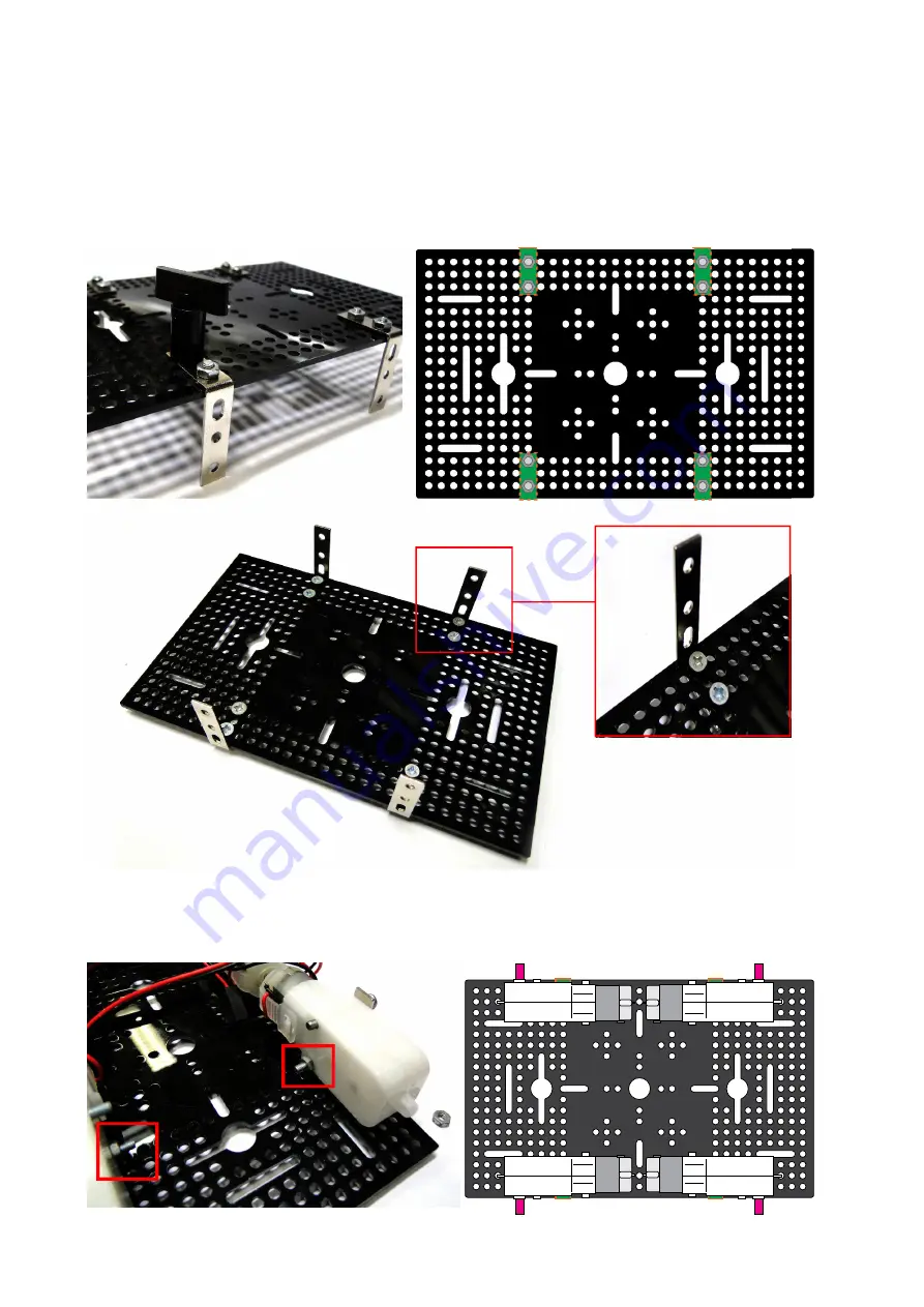
(4.3.3) Attach the metal angle bracket 2x3N with ATX chasis by using 8 sets of 3x6mm. screws

and 3mm. nuts at the position following the picture below. The bracket is placed under the

chasis and insert screw from top side through the hole of ATX chasis

(4.3.4) Mount the DC motoe gearbox at each bracket. The motor shaft is located to outside.

Tighten  by  3

x

25mm.  screw  and  3mm.  nut  only  bottom  hole  first.  Moust  all  4  DC  motor

gearboxes.

Tighten the nut only bottom hole

Summary of Contents for IOIO-BOT

Page 1: ...IOIO BOT Android Robotics 1 IOIO BOT Android Robotics...

Page 2: ...2 IOIO BOT Android Robotics...

Page 3: ...board introduction 5 Chapter 2 Android development tools installation 13 Chapter 3 IOIO RAB IOIO Robotic Activity Board introduction 23 Chapter 4 Buiding IOIO BOT 29 Chapter 5 IOIO BOT interface test...

Page 4: ...4 IOIO BOT Android Robotics...

Page 5: ...dition the IOIO Q can interact with peripheral devices in the same way as most MCUs Digital Input Output PWM Analog Input I2C SPI and UART control can all be used with the IOIO Q Code to control these...

Page 6: ...Bluetooth dongle in IOIO BOT kit is tested and work well An existing application code written to work over USB does not need to change to add Bluetooth support if it is using the IOIOLib Application...

Page 7: ...3 RE7 SCL3 RE6 RE5 RE4 3 2 1 64 RE3 63 RE2 62 RE1 61 RE0 60 26 25 24 23 22 21 20 19 RC15 40 RC14 48 RC13 47 RC12 39 2 9 8 1 RG9 8 RG8 6 RG7 5 RG6 4 30 29 28 27 SCL2 RF5 32 SDA2 RF4 31 RF1 59 RF0 58 48...

Page 8: ...5V support Compare input Firmware program med pin Peripheral input pin Recived serial data pin of UART module SPI port pin and Input Capture Peripheral output pin Transmit serial data pin of UART mod...

Page 9: ...ut 5V support Compare input Firmware program med pin Peripheral input pin Recived serial data pin of UART module SPI port pin and Input Capture Peripheral output pin Transmit serial data pin of UART m...

Page 10: ...ins 16 of Analog inputs Range is 0 to 3 3V Operated with 10 bit Analog to Digital Converter module within the main microcontroller 9 of PWM outputs with 10 bit resolution 4 of UART ports for serial co...

Page 11: ...actived by logic 0 IOIO Q use this LED as Status LED IOIO Q provides total 48 I O pin Include 16 of analog input pins 9 of PWM outputs 4 of UART serial communication ports and 3 of I2 C bus ports The...

Page 12: ...12 IOIO BOT Android Robotics...

Page 13: ...s Eclipse one of Java application development tool combined with the Android SDK software development kit for Android applications by Google The result is applications for Android devices in particula...

Page 14: ...the computer after the uninstall is complete Before you start to install the Java Runtime Environment JRE version checking the latest version of JRE from http www oracle com technetwork java javase d...

Page 15: ...IO BOT Android Robotics 15 3 Download the operating system used In this example is Windows 8 1 in 64 bit Choose to download a Windows x64 4 Run the installation file and click on Install button to sta...

Page 16: ...ose button to finish 2 2 1 2 Android Development Tools ADT installation 1 Download the Android Development Tools ADT from http developer android com sdk index html Click on the Download the SDK ADT Bu...

Page 17: ...ox I have read and agree with the above terms and conditions Then choose the version of the operating system 32 or 64 bits Next click on the Download the SDK ADT Bundle for Windows button to start dow...

Page 18: ...peared It is window that determines the development of Java applications folder to store the created files In this example is C User user workspace Recommend assigning a drive other than C as defined...

Page 19: ...IOIO BOT Android Robotics 19 6 ADT program will be open with the Welcome window It is installation completely...

Page 20: ...stem is installed successfully 2 2 2 1AndroidDevelopmentTools ADT installation 1 Download the Android Development Tools ADT from http developer android com sdk index html Click on the Download the SDK...

Page 21: ...IOIO BOT Android Robotics 21 3 Double click at file to extract 4 Enter to the ADT folder Run the Eclipse executre file...

Page 22: ...ions folder to store the created files In this example is C User user workspace Recommend assigning a drive other than C as defined as the D drive This window shows up asking for every time that start...

Page 23: ...includes the socket for installtion IOIO or IOIO Q board power supply circuit DC motor driver mini board and Servo motor connector This chapter describes about technical details of IOIO RAB before go...

Page 24: ...6 and AN7 is used for analog sensor that requires 5V supply but give only 0 to 3 3V output voltage maximum For example the distance sensor GP2D120 GP2Y0A41 or GP2Y0A21 18 of Digital input output port...

Page 25: ...otor indicators Support DC motor 4 5 to 9V 1A each Low battery monitor circuit with indicator Supply voltage 6 5 to 12V On board 6V regulator circuit for IOIO Q board and Servo motors There are 2 type...

Page 26: ...RVO4 SERVO3 SERVO2 SERVO1 3 3V 3 3V 3 3V 3 3V 3 3V 3 3V 3 3V 3 3V AN7 AN6 AN0 AN1 AN2 AN3 AN4 AN5 3 3V 21 22 23 24 R5 R4 R4 R5 4 7k x2 K19 SCL2 K20 SDA2 K3 IOIO Q port1 K4 IOIO Q port2 K5 IOIO Q port3...

Page 27: ...DC motor driver circuit IOIO RAB uses 3 of mini TB6612 boards IOIO Q I O pin1 to 6 for first 2 DC motor driver channels and pin8 to 19 for 4 channels See the Table 3 1 for details of connections Each...

Page 28: ...ith IOIO Q I O pin27 via C7 capacitor In normal operation and in IOIO BOT user must plug the IOIO Q board on top of IOIO RAB Plug the Bluetooth dongle at IOIO Q s USB connector Apply the supply voltag...

Page 29: ...cluded 4 1 IOIO BOT key features Control the robot movement by Android devices through a USB port ADB or wirelessly over Bluetooth Bluetooth control is recommended Powered by IOIO Q board and IOIO Rob...

Page 30: ...x5 x 4 Metal angle bracket 2x2 x 4 Metal angle bracket 2x3N x 4 Metal angle bracket 2x1 x 4 3mm nut x 30 3mm Locknut x 2 3x32mm metal Standoff x 2 2mm tappinng screw x 4 3x6mm screw x 9 3x10mm screw x...

Page 31: ...mm screws and 3mm nuts at the less depth side Do the same for all four wheels To tighten all screws and nuts recommended plastic nut driver can be more convenient Spike wheel and tire set Insert tire...

Page 32: ...tion following the picture below The bracket is placed under the chasis and insert screw from top side through the hole of ATX chasis 4 3 4 Mount the DC motoe gearbox at each bracket The motor shaft i...

Page 33: ...ition 4 3 5 Attach 2 pieces of the metal angle bracket 2x5 by using 3x6mm screws and 3mm nuts following the picture below Do the same for 2 sets 3mm nuts 3x6mm screws 4 3 6 Mount the assemblied bracke...

Page 34: ...picture below by using 3x6 mm screws No need to tighten the screws because may move it later 4 3 8 Insert the spike wheel with DC motor gearbox shaft Tighten with 2mm tapping screw Do all 4 wheels 4 3...

Page 35: ...position is oppsite with standoff Next mount the IOIO RAB with both brackets by using 3x10mm screws and 3 mm nuts 4 3 12 Connect the battery holder wires to IOIO RAB at battery terminal Must check th...

Page 36: ...Li PO battery pack If using Li PO battery pack connection the battery to DEAN connector is recommended 4 3 14 Place the controller board down Adjust the board position to all holes position are match...

Page 37: ...ct with M2 output Red pole is outside and black pole is inside Back left motor connect with M5 output Red pole is outside and black pole is inside Front left motor connect with M6 output Red pole is o...

Page 38: ...38 IOIO BOT Android Robotics...

Page 39: ...re for supporting the connection before The interfacing of both devices operate on ADB or Android Debug Bridge The preparation of the Android device is divided according to the version of Android degv...

Page 40: ...4 0 Ice Cream Sandwich or higher Enter to menu Developer options Tab to check mark at USB Debugging following the figure 5 2 Figure 5 2 Example of how to enable the USB Debugging of the Android devic...

Page 41: ...gs About phone or tablet Then tap the Build number 7 times A message pops up that says the user is then developer Back to the Settings page the menu Developer options is appeared Tap to select and do...

Page 42: ...ing USB Debugging option again 5 3 Interfacing Android device with IOIO BOT wirelessly over Bluetooth 5 3 1 Plug the USB Bluetooth dongle to USB connectot of IOIO Q on the IOIO BOT following the figur...

Page 43: ...tics 43 5 3 3 In paring the Bluetooth devices require the pairing code It is 4545 Type this code in the box and tap OK button Figure 5 6 Procedure about paring the Bluetooth connection between IOIO BO...

Page 44: ...o find Bluetooth dongle again If all correct Android device will found the dongle with computer name In the case of Android device used to connect to a Bluetooth of this computer before User must canc...

Page 45: ...IOIO BOT Android Robotics 45 Figure 5 7 Summary of steps about Android device cannot found the Bluetooth dongle troubleshooting...

Page 46: ...46 IOIO BOT Android Robotics...

Page 47: ...he recommended applications about IOIO BOT controlling that Innovative Experiment or INEX developed and explained in this chapter is IOIO Bot application 6 1 IOIO Bot application overview The IOIO Bot...

Page 48: ...he top and bottom of the chosen choose maximum speed with opposite direction When move slider to top the IOIO BOT will move forward and move backward if move slider to bottom position Figure 6 2 Illus...

Page 49: ...ling both motor operations separately It causes many movement direction for IOIO BOT It also determines the speed during movement easy See the summary of movement in figure 6 4 Figure 6 4 IOIO BOT mov...

Page 50: ...Bot application How it work About the operation of IOIO Bot app should be explain as 2 parts One is Android device operation and IOIO Q operation Refer the flowchart in figure 6 5 in explanation Figur...

Page 51: ...IOIO BOT Android Robotics 51 Figure 6 5 IOIO Bot app flowchart final...

Page 52: ...within the Linear Layout only following the figure 6 6 For Event Listener that used with the Linear Layout is OnTouchListener It activate when any touching screen is appeared such as user tap on the L...

Page 53: ...board operation For working with IOIO Bot app set the IOIO Q I O pins to interface with DC motor driver boards For IOIO BOT used only M1 M2 M5 and M6 output The pin assignment is show below 1 IOIO Q p...

Page 54: ...ove motor cable from IOIO RAB and run again If LED operate correct and do not work after plug the motor cable back to IOIO BOT It might be due to insufficient power Check the battery or change if nece...

Page 55: ......

Page 56: ......

Reviews: