BOBCAT Hardware User’s Manual
Imperx, Inc.
Rev. 2.0.6
6421 Congress Ave.
11/20/2012
Boca Raton, FL 33487
+1 (561) 989-0006
120 of 265
2.8
GAIN and OFFSET
2.8.1 Analog Domain
– manual control
The camera has dual analog signal processors (or Analog Front End – AFE), one per
channel. It features one dual processor, each containing a differential input sample-
and-hold amplifier (SHA), digitally controlled variable gain amplifier (VGA), black
level clamp and a 14-bit ADC. The programmable internal AFE registers include
independent gain and black level adjustment. There are 1024 possible gain levels
(
gcode
0 to 1023) and 1024 offset (clamp) levels (
ocode
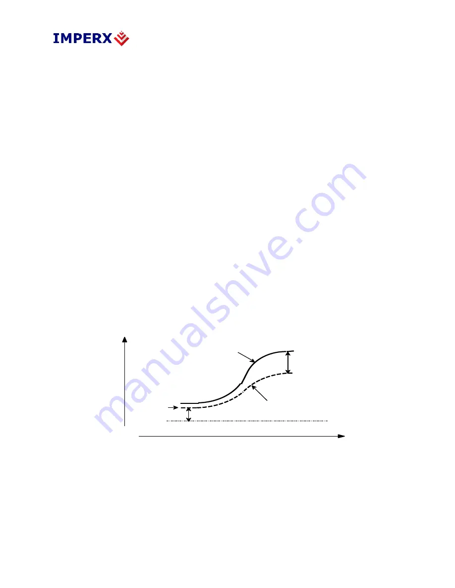
0 to 1023). Figure 2.20
shows the relationship between the video signal output level and gain/offset.
Theoretically, the black level should reside at 0 volts and the gain changes should
only lead to increasing the amplitude of the video signal. Since the camera has two
separate video outputs coming out of the CCD, there is always some offset
misbalance between the video outputs. Thus, changing the AFE gain leads to a
change in the offset level and to a further misbalance between the two video signals.
To correct the balance between two signals for a particular gain, the user should
always adjust the offset for each output – refer to the Camera Configuration section.
The overall camera gain can be calculated using formula 2.3, where Fixed Gain (FG)
is user selectable (- 3dB, 0, 3 dB, or 6dB).
VGA Gain [dB] = FG [dB] + 0.0351 x
gcode
(2.3)
light intens ity
vid
eo
o
utp
ut
b lack level
p ix el o u tp u t
0 V
AFE g ain
AFE o u tpu t
~ 2 0 mV o ffset
Figure 2.20 – AFE gain and offset


