


IDT Transparent Mode Operation
Generic PCI to PCI Bridge Register Definition
PES12N3 User Manual
9 - 39
June 7, 2006
Notes
Message Signaled Interrupt Capability Structure
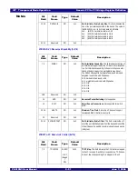
MSICAP - Message Signaled Interrupt Capability and Control (0x07C)
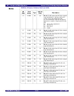
MSIADDR - Message Signaled Interrupt Address (0x080)
31
MCS
RW
0x0
Mode Configuration Switch. When this bit is set to zero,
the PMPC register is configured as Mode1, shown in the
Mode1 table. When this bit is set to one, the register is con-
figured as Mode2, shown in this table.
Bit
Field
Field
Name
Type
Default
Value
Description
7:0
CAPID
RO
0x5
Capability ID. The value of 0x5 identifies this capability as
a MSI capability structure.
15:8
NXTPTR
RO
0x0
Next Pointer. This field contains a pointer to the next
capability structure. This field is set to 0x0 indicating that it
is the last capability.
16
EN
RW
0x0
Enable. This bit enables MSI.
0x0 - (disable) disabled
0x1 - (enable) enabled
19:17
MMC
RO
0x0
Multiple Message Capable. This field contains the num-
ber of requested messages. The transparent bridge
requests one message.
22:20
MME
RO
0x0
Multiple Message Enable. Hardwired to one message.
23
A64
RO
0x1
64-bit Address Capable. The transparent bridge is capa-
ble of generating messages using a 64-bit address.
31:24
Reserved
RO
0x0
Reserved.
Bit
Field
Field
Name
Type
Default
Value
Description
1:0
Reserved
RO
0x0
Reserved.
31:2
ADDR
RW
0x0
Message Address. This field specifies the lower portion of
the DWORD address of the MSI memory write transaction.
Bit
Field
Field
Name
Type
Default
Value
Description
Summary of Contents for 89HPES12N3
Page 10: ...IDT Table of Contents PES12N3 User Manual iv June 7 2006 Notes...
Page 14: ...IDT List of Figures PES12N3 User Manual viii June 7 2006 Notes...
Page 36: ...IDT Clocking Reset and Initialization Reset PES12N3 User Manual 2 8 June 7 2006 Notes...
Page 40: ...IDT Link Operation Slot Power Limit Support PES12N3 User Manual 3 4 June 7 2006 Notes...
Page 50: ...IDT Switch Operation Switch Core Errors PES12N3 User Manual 4 10 June 7 2006 Notes...
Page 54: ...IDT Power Management Active State Power Management PES12N3 User Manual 5 4 June 7 2006 Notes...
Page 62: ...IDT Hot Plug and Hot Swap Hot Swap PES12N3 User Manual 6 8 June 7 2006 Notes...
Page 78: ...IDT SMBus Interfaces Slave SMBus Interface PES12N3 User Manual 7 16 June 7 2006 Notes...
Page 148: ...IDT Test and Debug SerDes Test Clock PES12N3 User Manual 10 6 June 7 2006...
Page 158: ...IDT JTAG Boundary Scan Usage Considerations PES12N3 User Manual 11 10 June 7 2006 Notes...