


48
Response FF80
- Installation
SERVICING
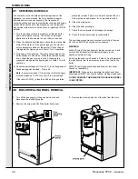
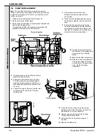
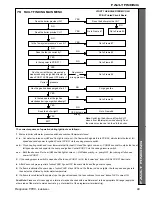
77 PRESSURE RELIEF VALVE (Safety valve) REPLACEMENT
SER
VICING
1.
Isolate the electrical supply. Refer to Frame 55.
2.
Remove pump. Refer to Frame 70.
3.
Disconnect the mains electrical connection from the
bottom panel. Disengage the 2 halves of the connector.
4.
Remove the boiler bottom panel.
5.
Close the cocks on the CH flow and return pipework
below the boiler. Drain down - refer to Frame 52.
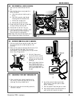
6.
Disconnect the discharge pipe to the pressure relief valve.
7.
Undo the connection securing the valve to the boiler.
8.
Replace with a new valve and restore the pipework, in
reverse order, using new sealing washer.
9.
Open cocks, fit filling loop, fill, vent and pressurise to 1 bar
(or as required).
10.
Restore the electrical supply and set the heating controls,
to test-fire the boiler.
11.
Vent air and top up the pressure again, as required.
12.
Remove the filling loop.
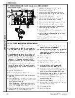
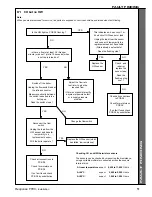
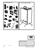
78 CH EXPANSION VESSEL REPLACEMENT
If the CH expansion vessel is faulty, there are 3 options:
A.
If it has a punctured diaphragm, but is
otherwise leak free,
then it can be left in place and a new vessel added to the
system, external to the boiler, provided it is of adequate
capacity and pre-charge pressure.
B.
If there is at least 600mm clearance above the boiler, the
expansion vessel can be changed without removing the
boiler (RH exit flues will have to be disturbed). Access to the
water connection of the expansion vessel is
either
by
removal of the right hand side boiler panel (if there is
200mm RHS clearance)
or
by removal of the fan and gas
valve.
C.
If there is insufficient headroom, the boiler will need to be
removed. In this case, access to the water connection of
the expansion vessel will be possible by removing the RH
boiler side panel.
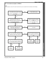
For option B, proceed as follows:
B1.
Isolate the electric, gas, and water services.
B2.
Drain down the boiler CH circuits, using the appropriate
drain cocks.
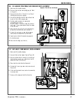
B3. Where RH clearance is available.
Unscrew the 6 screws
securing the RHS panel and remove panel to gain access
to expansion vessel connector.
Where RH clearance is not available.
Remove the fan
(refer Frame 49) and gas valve (refer Frame 63) to gain
access to the expansion vessel connector.
B4.
Disconnect the flue, if RH exit, and remove to the right
(general details are reverse of Frames 18 & 28).
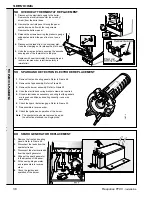
B5.
Undo the 3 screws securing the boiler panel above the
expansion vessel, and remove the panel.
B6.
Undo the water connection at the bottom of the expansion
vessel. Lift out the vessel and fit the replacement,
reassembling in reverse order - using new gaskets and 'O'
rings where appropriate.
B7.
Fill, pressurise and test.
B8.
Remove the filling loop.
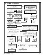
For option C, proceed as follows:
C1.
Isolate the electrical, gas and water services.
C2.
Drain down the boiler CH/HW circuits using the
appropriate boiler drain cocks (refer Frame 52).
C3.
Undo all service unions at the base of the boiler, and
unplug and disconnect the electrical supply lead, which is
secured by one screw in the centre of the boiler base.
C4.
Disconnect the flue turret and place to one side (reverse
of the assembly described in Frames 18 & 28).
C5.
Lift the boiler off the wall and place horizontally, at a
convenient working height.
C6.
Follow instructions B3 to B6.
C7.
Return the boiler to the wall mounting frame, remaking all
connections, including the flue.
C8.
Fill, pressurise and test.
C9.
Remove the filling loop.