


28
Response FF80
- Installation
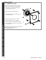
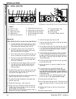
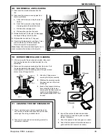
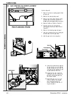
35 WATER CONNECTIONS
INSTALLATION
INST
ALLA
TION
Refer to General Note, Frame 34, for guidance.
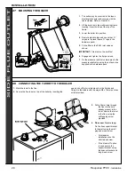
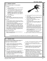
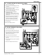
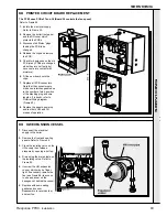
37 SAFETY VALVE DRAIN
The discharge pipe should be positioned so that the discharge of water or steam cannot create a hazard
to the occupants of the premises or damage to electrical components and wiring.
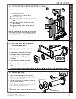
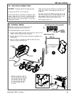
For top connections:
reverse 22mm pipe.
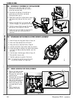
Bottom and Top connections
2.
Remove the gas cock bracket complete with gas cock.
3.
Screw connector into gas cock in the correct orientation.
4.
Screw complete assembly back onto the mounting frame.
Extend a gas supply pipe of not less than 22mm O.D. copper or
3/4" BSP iron to the boiler.
A working gas pressure of 20mbar (8" w.g.) must be available at
the boiler inlet with the boiler firing at full DHW output.
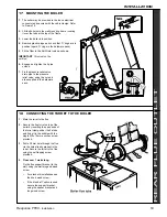
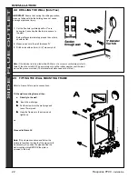
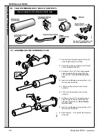
36 GAS CONNECTION
Refer to General Note, Frame 34, for guidance.
Bottom connection
1a.
Solder the 1/2" connector and reducing coupling to the
preformed pipe provided
OR:
Top connection
- suggested method
1b.
Solder the 1/2" connector and reducing coupling to straight
pipe and elbow not provided.
DHW CONNECTIONS
CH CONNECTIONS
Note.
Do not subject any of the isolating valves to heat as the seals may be damaged .
For top connections:
use 15mm straight pipe and
elbow (not supplied).