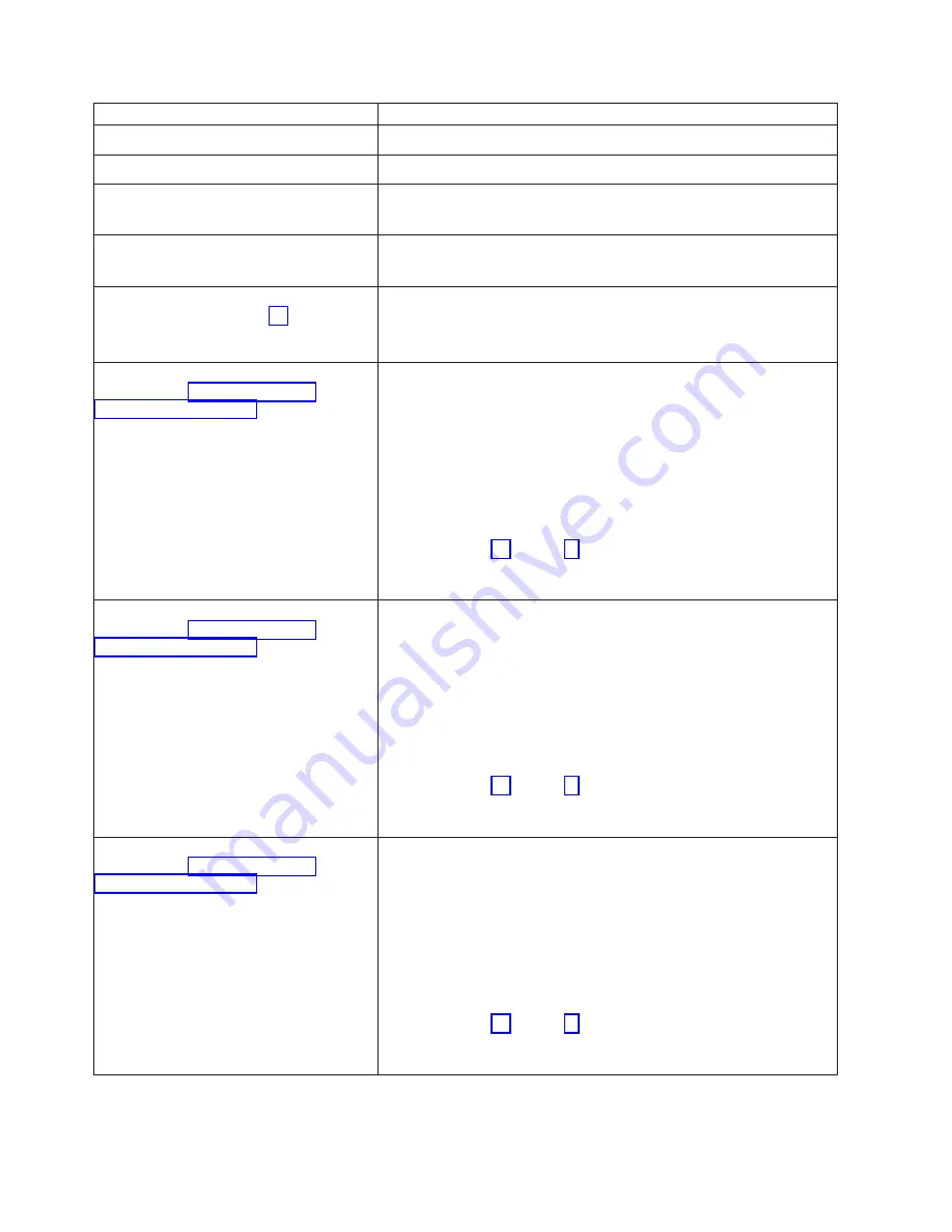
IBM xSeries 440 8687 Hardware Maintenance Manual Download Page 182

Error


code/symptom


FRU/action


180-xxx-007


(Failed


Centerplane


LED


test)


v


Centerplane


180-xxx-008


(Failed


I/O


board


LED


test)


v


I/O


board


180-xxx-009


(Failed


Active


PCI


LED


test)


1.


Active


PCI


assembly


2.


PCI-X


board


180-361-003


(Failed


Fan


LED


test)


1.


Fan


2.


I/O


board


201-xxx-Ynn


(failed


Memory


Test;


see


“Memory


settings”


on


page


18)


Note:


Y


=


SMP


Board


[0=Bottom


SMP


Board;


1=Top


SMP


Board]


1.


DIMM


nn


[nn


=


failing


DIMM]


(see


System


Error


log


for


location)


2.


SMP


Board


201-XXX-Y21


(Multiple


DIMM


failure


in


Port


1


Bank


1;


see


“DIMM


removal


and


replacement”


on


page


93)


Note:


Y


=


SMP


Board


[0=Bottom


SMP


Board;


1=Top


SMP


Board]


1.


Isolate


failing


DIMM:


a.


Replace


a


DIMM


in


bank


with


a


known


good


DIMM.


b.


Rerun


memory


diagnostic


for


the


failing


bank


on


failing


SMP


Board.


c.


If


test


fails,


mark


replaced


DIMM


as


good


DIMM.


d.


If


test


passes,


mark


replaced


DIMM


as


bad


DIMM.


e.


If


DIMM


tested


is


bad

,


remove


it


and


replace


it.


f.


If


DIMM


tested


is


good

,


do


not


replace


it.

2.


Repeat


steps


1a


through


1f


with


other


DIMMs


in


failing


bank


until


error


is


fixed.


3.


If


error


is


not


fixed,


replace


SMP


Board


Y.


201-XXX-Y22


(Multiple


DIMM


failure


in


Port


1


Bank


2;


see


“DIMM


removal


and


replacement”


on


page


93)


Note:


Y


=


SMP


Board


[0=Bottom


SMP


Board;


1=Top


SMP


Board]


1.


Isolate


failing


DIMM:


a.


Replace


a


DIMM


in


bank


with


a


known


good


DIMM.


b.


Rerun


memory


diagnostic


for


the


failing


bank


on


failing


SMP


Board.


c.


If


test


fails,


mark


replaced


DIMM


as


good


DIMM.


d.


If


test


passes,


mark


replaced


DIMM


as


bad


DIMM.


e.


If


DIMM


tested


is


bad

,


remove


it


and


replace


it.


f.


If


DIMM


tested


is


good

,


do


not


replace


it.

2.


Repeat


steps


1a


through


1f


with


other


DIMMs


in


failing


bank


until


error


is


fixed.


3.


If


error


is


not


fixed,


replace


SMP


Board


Y.


201-XXX-Y23


(Multiple


DIMM


failure


in


Port


1


Bank


3;


see


“DIMM


removal


and


replacement”


on


page


93)


Note:


Y


=


SMP


Board


[0=Bottom


SMP


Board;


1=Top


SMP


Board]


1.


Isolate


failing


DIMM:


a.


Replace


a


DIMM


in


bank


with


a


known


good


DIMM.


b.


Rerun


memory


diagnostic


for


the


failing


bank


on


failing


SMP


Board.


c.


If


test


fails,


mark


replaced


DIMM


as


good


DIMM.


d.


If


test


passes,


mark


replaced


DIMM


as


bad


DIMM.


e.


If


DIMM


tested


is


bad

,


remove


it


and


replace


it.


f.


If


DIMM


tested


is


good

,


do


not


replace


it.

2.


Repeat


steps


1a


through


1f


with


other


DIMMs


in


failing


bank


until


error


is


fixed.


3.


If


error


is


not


fixed,


replace


SMP


Board


Y.


170


xSeries


440


Type


8687:


Hardware


Maintenance


Manual

Summary of Contents for xSeries 440 8687

Page 1: ...xSeries 440 Type 8687 Hardware Maintenance Manual ERserver...

Page 2: ......

Page 3: ...xSeries 440 Type 8687 Hardware Maintenance Manual ERserver...

Page 4: ...naccuracies or typographical errors Changes are periodically made to the information herein these changes will be incorporated in new editions of the publication IBM may make improvements and or chang...

Page 5: ...rtarsi di leggere tutti gli avvisi di attenzione e di pericolo prima di effettuare qualsiasi operazione Lea atentamente todas las declaraciones de precauci n y peligro ante de llevar a cabo cualquier...

Page 6: ...iv xSeries 440 Type 8687 Hardware Maintenance Manual...

Page 7: ...Setup main menu 16 Using passwords 19 Power on password 19 Administrator password 20 16 way configuration Models 1VX 2VX 3VX only 20 16 way considerations 20 16 way terms 21 Installing a 16 way config...

Page 8: ...a partitioned environment 52 Error logs 54 Viewing error logs from the Configuration Setup Utility program 54 Viewing error logs from the diagnostic programs 54 Light path diagnostics 54 Small compute...

Page 9: ...3 USB port connectors 114 SMP Expansion port 114 Cabling the server 115 Working with cables 115 SMP Expansion port cabling 116 16 way SMP Expansion port cabling models 1VX 2VX 3VX only 117 RXE Expansi...

Page 10: ...th card 149 Symptom to FRU index 151 Beep symptoms 152 No beep symptoms 154 Light Path LED errors 155 Level 1 light path 155 Level 2 light path 155 Level 3 light path 157 System Error log entries 158...

Page 11: ...Grounding requirements 204 Safety notices multi lingual translations 205 Problem determination tips 235 Notices 236 Trademarks 237 Index 239 Contents ix...

Page 12: ...x xSeries 440 Type 8687 Hardware Maintenance Manual...

Page 13: ...more external storage units are attached to the server and at least one of the attached storage units is also attached to another server or unidentifiable source v One or more servers are located near...

Page 14: ...error log indicates a damaged field replaceable unit FRU replace the FRU and run diagnostics to confirm that the problem has been solved b If the error log does not indicate a damaged FRU check the o...

Page 15: ...enterprise index html If you have access to the World Wide Web you can obtain up to date information about the xSeries 440 model and other IBM server products at the following World Wide Web address h...

Page 16: ...v Compatible with SVGA v 8 MB SDRAM video memory at 125 MHz Size 4U v Height 17 8 cm 7 inches 4U v Depth 69 85 cm 27 5 inches v Width 48 3 cm 19 inches v Maximum weight 50 kg 110 lb depending on your...

Page 17: ...ent and data storage The server includes v IBM Enterprise X Architecture Enterprise X Architecture is an IBM design blueprint that takes full advantage of existing IBM technologies to build the most p...

Page 18: ...he Remote Supervisor Adapter also provides system monitoring event recording and dial out alert capability v Integrated network environment support The server comes with an integrated Broadcom Gigabit...

Page 19: ...t indicates that the hard disk drive is in use Hard disk drive error light When this amber light is on it indicates that there is a problem with the hard disk drive USB port This is an automatically c...

Page 20: ...s used to secure the power supply in place Reset button Press this button to reset the server and run the power on self test POST You might need to use a pen or the end of a straightened paper clip to...

Page 21: ...r the Ethernet port v Ethernet activity light This green light located on the left of the Ethernet port goes on when there is activity on the Ethernet LAN connected to the Ethernet port v 10 100 Ether...

Page 22: ...being detected If this happens take the following actions a Open the light path diagnostics panel see Light path diagnostics on page 54 and verify that the Event Log LED is illuminated b Check the sy...

Page 23: ...of the server is lit Turning off the server Note Pressing the power control button on either the primary or secondary server in the 16 way configuration models 1VX 2VX 3VX only will turn on or turn o...

Page 24: ...nterface Complete the following steps to put the server into Standby mode 1 See the operating system documentation for the proper procedure to shut down the operating system Note Each operating system...

Page 25: ...not available in the language for that region the English version is displayed Click Help for detailed information about using the IBM Documentation Browser Complete the following steps to use the Do...

Page 26: ...14 xSeries 440 Type 8687 Hardware Maintenance Manual...

Page 27: ...erver model came with an operating system installed such as Microsoft Windows 2000 Datacenter Server see the software documentation provided with the server for configuration information v IBM ServerG...

Page 28: ...for Configuration Setup appears press F1 3 Follow the instructions that appear on the screen Choices available from the Configuration Setup main menu From the Configuration Setup Utility main menu yo...

Page 29: ...nd Diskette controllers Notes 1 The default setting is Enable for all the controllers If you select Disable the system will not configure the disabled device and the operating system will not detect t...

Page 30: ...n the screen carefully System Partition Visibility With certain versions of ServerGuide you can select this choice to identify if the System Partition is visible To make the System Partition visible s...

Page 31: ...g the changes Using passwords The System Security choice appears only on the full Configuration Setup Utility menu After you select this choice you can set a power on password or an administrator pass...

Page 32: ...password to access the Configuration Setup Utility program v All choices are available on the Configuration Setup Utility main menu Administrator and power on password v You can type either password t...

Page 33: ...tition is configured through the partition descriptor found in BIOS This static partition defines how the servers are connected to share their resources Partition descriptor A partition descriptor def...

Page 34: ...a server and watch the monitor screen b When the message Press F1 for Configuration Setup appears press F1 c Select Advanced Setup from the menu then select CPU Options and enable hyper threading Note...

Page 35: ...to cable two xSeries 440 servers together in a 16 way configuration 1 Label each end of the long SMP Expansion cables according to where they connect to each server see the following illustration Not...

Page 36: ...a long SMP Expansion cable to port 1 of SMP Expansion Module 1 on the primary server then route the cable through the cable management arm as in step a d Connect one end of a long SMP Expansion cable...

Page 37: ...port 3 of SMP Expansion Module 3 4 Route any remaining cables through the cable management arms 5 Secure the cables in the cable management arms with the hook and loop straps that come with your serve...

Page 38: ...t menu The following choices appear on the SCSISelect Utility menu v Configure View Host Adapter Settings Select this choice to view or change the SCSI controller settings To reset the SCSI controller...

Page 39: ...crosoft Windows 2000 Datacenter Server see the software documentation provided with the server for configuration information Using the ServerGuide CD The ServerGuide CD models 1RX 2RX 3RX 4RX 5RX 6RX...

Page 40: ...e CD to configure any supported IBM server model The setup program provides a list of tasks that are required to set up the server model On RAID servers you can run the ServeRAID Manager program to cr...

Page 41: ...a separate diagnostics CD System Partition The ServerGuide program creates a 50 MB System Partition on the default drive The System Partition contains server specific utility programs such as Remote...

Page 42: ...u click xSeries 440 4 On the left side of the page click OS Installation to see the list of installation instructions for the supported operating systems 5 From the Operating System installation by Ca...

Page 43: ...gement CD v To configure the remote alert recipients for Director over LAN or Director over modem the remote alert recipient must be an IBM Director enabled server with UM Server Extensions v If you w...

Page 44: ...Installing Advanced System Management device drivers on page 39 Cabling the Ethernet LAN port and serial port This section describes how to cable the Remote Supervisor Adapter You can manage the serv...

Page 45: ...sor Adapter Connect the other end of the Ethernet cable to the network 2 Check the Ethernet LEDs to ensure that the network connection is working The following illustration shows the location of the L...

Page 46: ...Web interface using point to point PPP protocol Text based user interface using the TELNET protocol over PPP Configuring the Ethernet settings for Web based remote access If you have an accessible act...

Page 47: ...rvisor Adapter User s Guide on the IBM Documentation CD 6 Change the DHCP Setting field to Disabled The default value is Enabled 7 Press F6 to apply the change 8 Press Esc After the Warning window ope...

Page 48: ...te The values in the window are only examples your settings might be different 5 Verify the following serial port values Baud Rate The default is 57600 Make sure that the baud rate matches the baud ra...

Page 49: ...rn to the Configuration Settings window If you need to set up point to point protocol go to Setting up point to point protocol 8 Press Esc to return to the Utility program main window 9 Use the arrow...

Page 50: ...Make sure that the value in this field matches your client settings For detailed information about the PPP settings see the information about configuring PPP access over a serial port in the Remote Su...

Page 51: ...ically v Windows 2000 Continue with Installing Windows 2000 ASM device drivers v Windows NT Go to Installing Windows NT ASM device drivers After you install the ASM device drivers go to Configuring th...

Page 52: ...the CD ROM drive Press Enter 2 Follow the instructions that appear in the window 3 Go to Configuring the remote control password Using the interactive method Complete the following steps to use the i...

Page 53: ...If you do not want to set up an ASM interconnect network Remote Supervisor Adapter configuration is now complete To start managing the server remotely see the Remote Supervisor Adapter User s Guide o...

Page 54: ...ng You must connect the servers to the ASM interconnect network in a series with terminated beginning and end points v Make sure that the total combined length of all Ethernet cables connecting the se...

Page 55: ...network where ASM processor 1 generates a modem alert but does not have a modem and the other ASM processors have modems the following might occur If ASM processor 1 generates an alert and the modem i...

Page 56: ...ng the ASM Interconnect module to the xSeries 440 The ASM Interconnect module connects the Remote Supervisor Adapter to the ASM interconnect network This module must be purchased separately To connect...

Page 57: ...s the LAN connection to forward system management data generated by the other xSeries 440s in the ASM interconnect network bus to the remote system management administrator Remote system management ad...

Page 58: ...if an ASM interconnect connection in the bus fails all of the servers on the ASM interconnect network have access to a modem to forward system management data to the remote system management administ...

Page 59: ...IBM 10 100 1000 EtherJet PCI family of adapters Teaming mode Your Ethernet controller provides options called teaming options that apply to supported Ethernet controllers A team can consist of two or...

Page 60: ...the Configuration page 7 Click Close and restart the computer Priority Packet mode Priority Packet is a traffic prioritization utility that enables you to set up filters to process high priority traf...

Page 61: ...nnector The following illustration shows the pin number assignments for the RJ 45 connector These assignments apply to both 10BASE T and 100 1000BASE TX devices 1 8 Link LED green Activity LED green C...

Page 62: ...50 xSeries 440 Type 8687 Hardware Maintenance Manual...

Page 63: ...erver gave the error before attempting any repairs or changing any settings POST When you turn on the server it performs a series of tests to check the operation of server components and some of the o...

Page 64: ...e column listing the SMP Expansion Modules numbered sequentially beginning with 1 and one column for that Module s merge status as in the following example SMP Exp Module Partition Merge Status 1 Prim...

Page 65: ...mary server BIOS 4 Failed BIOS version is older than primary server BIOS SMP Exp Module Partition Merge Status 1 Primary lower 2 Primary upper 3 Failed Timed out 4 Failed Timed out An overall status m...

Page 66: ...help identify the source of an error The lights are designed to be followed in an orderly progression depending on the error The lights are viewed in the following order 1 Begin on the front panel see...

Page 67: ...ont of the light path diagnostics drawer and the light path diagnostic panel will be exposed More information about the individual lights on this panel is available at Light Path LED errors on page 15...

Page 68: ...ves an overview of internal components that correspond to each of the six LEDs on the top of the server This information combined with the information contained in the table Light Path LED errors on p...

Page 69: ...ext message where fff is the three digit function code that indicates the function being tested when the error occurred For example function code 089 is for the microprocessor ttt is the three digit f...

Page 70: ...gnostic test discovers an error User Aborted This result occurs when you stop the diagnostic test before it is complete Not Applicable This result occurs when you specify a diagnostic test for a devic...

Page 71: ...and monitor to the secondary server in order to run diagnostic programs on that server The procedure for starting diagnostics is the same for both servers and the merge process can be stopped from eit...

Page 72: ...ou are in the diagnostic programs When you exit the diagnostic programs the test log is cleared saved test logs are not affected To save the test log so that you can view it later click Save Log on th...

Page 73: ...02 Scalab_1 P2 Ext yes yes 1600 MHz no no 00 03 Scalab_1 P3 Scalab_2 P3 Ext yes yes 1600 MHz no no 00 04 Scalab_2 P1 Ext yes yes 1600 MHz no no 00 05 Scalab_2 P2 Ext yes yes 1600 MHz no no 00 06 Scal...

Page 74: ...is described in the following list Note The Connected to information is not known for ports that had been connected to the other server prior to booting as a standalone server for the diagnostic prog...

Page 75: ...00 MHz no no 00 08 Memory_1 P1 PCI X__2 P0 Int yes yes 500 MHz no no 00 09 Memory_2 P0 PCI X__2 P1 Int yes yes 500 MHz no no 00 10 Memory_2 PB RXE100_A PA Ext yes yes 500 MHz no no 00 PCI X 11 PCI X__...

Page 76: ...o no 00 PCI X 11 PCI X__1 P0 Memory_1 P0 Int yes yes 1000 MHz no no 00 12 PCI X__1 PA Ext yes yes 250 MHz no no 00 13 PCI X__2 P0 Memory_1 P1 Int yes yes 500 MHz no no 00 14 PCI X__2 P1 Memory_2 P0 In...

Page 77: ...eB shown below is not present v If the port being tested blocks access to the chip controlling that port that entry will be greyed out An example is shown below RXE100 SideA Port Testing that port wil...

Page 78: ...rnal cables and power cords then remove the cover see Opening the cover on page 72 2 Remove fans 3 and 4 see Fans 3 and 4 on page 105 3 Locate the BIOS code page jumper J28 on the I O board Jumper J28...

Page 79: ...k the port label If the label contains an X the hub has an X port v Determine if the hub supports auto negotiation If not try configuring the integrated Ethernet controller manually to match the speed...

Page 80: ...68 xSeries 440 Type 8687 Hardware Maintenance Manual...

Page 81: ...s This section provides basic information that is needed to install certain components For a list of supported options for this server see the ServerProven list at http www ibm com pc compat Copyright...

Page 82: ...T H IN 2 M IN U T E S F R O N T O F B O X N O T E F O R P R O P E R A IR F LO W R E P LA C E FA N W IT H IN 2 M IN U T E S F R O N T O F B O X EMC Shield For single SMP Module SMP baffle Retention bra...

Page 83: ...erver that is turned on v Avoid loose fitting clothing on your forearms Button long sleeved shirts before working inside the server do not wear cuff links while you are working inside the server v Do...

Page 84: ...E S F R O N T O F B O X Latch 2 Slide the server out from the rack 3 Pull the release latch on the left half of the top cover to the right 4 Using the finger hole in the release latch open the left ha...

Page 85: ...of the server SMP Expansion Module Retention bracket Retention bracket removal handles Shipping thumbscrews N O T E F O R P R O P E R A IR F LO W R E P LA C E FA N W IT H IN 2 M IN U T E S F R O N T...

Page 86: ...opposite edges of the bezel and pull this edge of the bezel slightly away from the server Note It may be easier to press the bottom tabs first 2 Press in on the two tabs at the other edge of the bezel...

Page 87: ...er requires a 220 V power connection for full power supply redundancy Whenever possible use a 220 V connection for all configurations However you can use a 110 V connection without power supply redund...

Page 88: ...pply out from the server Power supply handle in open position AC LED DC LED Hot swap power supply Release latch 4 To install the new power supply a Place the handle on the power supply in the open pos...

Page 89: ...tructions in this chapter v If you need to change the switch settings or jumper settings on your adapter follow the instructions that come with the adapter v Video adapters are not supported v Some lo...

Page 90: ...ion v You can install an adapter with a speed faster than the label on a particular PCI X slot However the device will only operate at the speed indicated on the label v If you install a 33 MHz and a...

Page 91: ...ion guidelines on page 71 Working inside a server with power on on page 71 and Safety information on page 201 2 You must disable the Active PCI X slots in the server using the operating system before...

Page 92: ...ch toward the rear of the server and open the tab d Remove the expansion slot cover e Carefully grasp the adapter by its top edge or upper corners and align it with the connector on the PCI X board No...

Page 93: ...backplane and the other end is attached to the connector for the integrated SCSI controller behind fans 3 and 4 v The second SCSI cable is preinstalled along the inside of the server chassis and both...

Page 94: ...other end of the preinstalled SCSI cable and connect it to the SCSI backplane SCSI backplane connector Front of server 8 Reinstall fans 3 and 4 9 If you have other options to install or remove do so n...

Page 95: ...e in the drive bay a Ensure that the handle on the hard disk drive tray is in the open position b Slide the drive into the bay until it stops c Push the handle on the front of the hard disk drive clos...

Page 96: ...r CD ROM or DVD ROM drive Drive considerations v The xSeries 440 server supports the installation of up to two CD ROM drives or two DVD ROM drives v If no other IDE drives are installed the diskette d...

Page 97: ...N W IT H IN 2 M IN U T E S F R O N T O F B O X N O T E F O R P R O P E R A IR F L O W R E P L A C E F A N W IT H IN 2 M IN U T E S F R O N T O F B O X External removable media bays CD ROM or DVD driv...

Page 98: ...SMP Expansion Module and one SMP baffle installed v An SMP Expansion Module must contain at least one microprocessor and four DIMMs v If it becomes necessary to remove or install DIMMs do so through t...

Page 99: ...e server and peripheral devices disconnect the power cords and all external cables from the SMP Expansion Module then open the cover see Opening the cover on page 72 for details 3 If necessary remove...

Page 100: ...O R P R O P E R A IR F L O W R E P L A C E F A N W IT H IN 2 M IN U T E S F R O N T O F B O X N O T E F O R P R O P E R A IR F L O W R E P L A C E F A N W IT H IN 2 M IN U T E S F R O N T O F B O X EM...

Page 101: ...P R O P E R A IR F LO W R E P LA C E FA N W IT H IN 2 M IN U T E S F R O N T O F B O X Latch Locking levers Handle Finger relief 7 Use the handle and the finger relief on the SMP Expansion Module cov...

Page 102: ...slightly from your hardware DIMM bank 2 DIMM considerations Before installing DIMMs read the following information v Your xSeries 440 server supports 512 MB and 1 GB DIMMs for a maximum of 32 GB of s...

Page 103: ...nges Therefore you must change and save the new configuration information by using the Configuration Setup Utility program When you restart the server the system displays a message indicating that the...

Page 104: ...s replaced Memory Mirroring then copies the mirrored data back into the new DIMM v Memory Scrubbing is an automatic regularly occurring test of all the system memory that detects and reports memory er...

Page 105: ...the server cover see Opening the cover on page 72 for details 3 If necessary remove the top SMP Expansion Module from the server Refer to Removing an SMP Expansion Module and cover on page 87 for inst...

Page 106: ...ion Module cover see Reinstalling an SMP Expansion Module and cover on page 101 9 If you have other options to install or remove do so now 10 Close the server cover See Closing the cover on page 106 N...

Page 107: ...and external clock frequencies as the microprocessors already installed in the individual SMP Expansion Module For a list of microprocessors supported by the server see the ServerProven list at http...

Page 108: ...dule cover and determine the socket where the microprocessor is to be installed For details see Removing an SMP Expansion Module and cover on page 87 Important Before continuing you should determine w...

Page 109: ...nting screw and remove the heat sink Microprocessor locking lever Captive screws Heat sink 3 Microprocessor 3 VRM 3 b Fully loosen one of the two captive mounting screws on the heat sink then pull up...

Page 110: ...be discarded When installing a new microprocessor you must install the VRM that came in the kit a If you are replacing a failed VRM 1 Verify that you have selected the correct VRM to be replaced The...

Page 111: ...eed To avoid bending the pins on the microprocessor do not use excessive force when pressing it into the socket d Close the locking lever to secure the microprocessor 9 If you have installed an additi...

Page 112: ...e cover on page 106 14 Turn on the server Important If the server will not start after replacing or installing a microprocessor you might have installed a microprocessor of a different type or the VRM...

Page 113: ...ation Setup Utility program on page 16 Complete the following steps to reinstall the SMP Expansion Module cover 1 Install the cover on the SMP Expansion Module a Set the cover on top of the expansion...

Page 114: ...N 2 M IN U T E S F R O N T O F B O X N O T E F O R P R O P E R A IR F LO W R E P LA C E FA N W IT H IN 2 M IN U T E S F R O N T O F B O X Latch Locking levers Handle Finger relief a Lift the SMP Expan...

Page 115: ...ack and connect all external cables For details see Closing the cover on page 106 and SMP Expansion port cabling on page 116 5 Turn on the server Note When you install or remove SMP Expansion Modules...

Page 116: ...side When the fan is operating correctly this light is off If a fan stops working the light path diagnostics feature will light a system error light on the front of the server indicating that there is...

Page 117: ...t of a failure you must replace the malfunctioning fan within 48 hours Complete the following steps to replace fans 3 and 4 1 Read the information in Installation guidelines on page 71 and Safety info...

Page 118: ...A N W IT H IN 2 M IN U T E S F R O N T O F B O X N O T E F O R P R O P E R A IR F L O W R E P L A C E F A N W IT H IN 2 M IN U T E S F R O N T O F B O X 2 Reconnect all external cables and power cord...

Page 119: ...osed of Do not v Throw or immerse into water v Heat to more than 100 C 212 F v Repair or disassemble Dispose of the battery as required by local ordinances or regulations Complete the following steps...

Page 120: ...ess the battery down into the socket 6 Replace fans 3 and 4 7 Reinstall the server cover and connect the cables 8 Turn on the server 9 Start the Configuration Setup Utility program and set configurati...

Page 121: ...nsion Port 1 SMP Expansion Port 2 SMP Expansion Port 3 SCSI port v Power connectors v RXE Expansion ports v Auxiliary device pointing device connector v Keyboard connector v Remote Supervisor Adapter...

Page 122: ...following illustration shows the pin number assignments for the auxiliary device connector on the end of the cable 6 4 2 1 3 5 Table 6 Auxiliary device connector pin number assignments Pin Signal 1 D...

Page 123: ...r to manage the server remotely or to connect the server to another server connect the appropriate cables to the Remote Supervisor Adapter ports To enable remote server management through a network us...

Page 124: ...modem cable to enable system management through a workstation or laptop computer Power LEDs The green power LED indicates the status of the power connection Gigabit Ethernet port The server comes with...

Page 125: ...ll no longer operate Disconnect all USB devices from the secondary server prior to merging the two servers The server has three Universal Serial Bus USB ports which are configured automatically USB is...

Page 126: ...ber assignments for the USB port connectors on the server 1 4 Table 9 USB port connector pin number assignments Pin Signal 1 VCC 2 Data 3 Data 4 Ground SMP Expansion port There are up to six SMP Expan...

Page 127: ...he server into an electrical outlet you must wait 30 seconds before pressing the power control button Working with cables This section describes how to connect cables to the SMP Expansion Port system...

Page 128: ...ower cables Attention Do not secure cables too tightly Overtightening can cause internal damage to the cables SMP Expansion port cabling Each server has up to six SMP expansion ports located on the ba...

Page 129: ...d between the SMP Expansion Module ports SMP data is interleaved between the cables for better performance 2 The SMP Expansion cables are not redundant 3 If either of the two cables is removed or fail...

Page 130: ...he remote I O enclosure Complete the instructions in this section to cable your server to a remote I O enclosure Cabling one SMP Expansion Module RXE 100 A in Port RXE Management RXE Expansion Port A...

Page 131: ...E Expansion Port on the remote I O enclosure Cabling an RXE 100 Remote Expansion Enclosure to a 16 way system Complete the following steps to connect an IBM RXE 100 Remote Expansion Enclosure to a 16...

Page 132: ...XE Port Primary A Secondary A Primary B RXE A Secondary B RXE B RXE Management port cabling models 1RX 2RX 3RX 4RX 5RX 6RX 7RX 3RY 4RY only The server has one RXE Management port located on the back o...

Page 133: ...erver 2 Plug the other end of the power supply cord into a properly grounded electrical outlet or a primary power unit inside the rack cabinet Note Plugging the power supply cords into an electrical o...

Page 134: ...ct the server to a keyboard or optional console switch You can also connect a USB keyboard to the server using one of the USB ports After installing a USB keyboard you might need to use the Configurat...

Page 135: ...rvisor Adapter 135 Remote Supervisor Adapter component locations 135 Riser card and Remote Supervisor Adapter replacement 136 Top cover assembly 138 Top power board 139 DASD backplane 140 Media bay ca...

Page 136: ...sink on a clean work surface 2 Remove the cleaning pad from its package and unfold it completely 3 Use the cleaning pad to wipe the thermal grease from the bottom of the heat sink Note Be sure that a...

Page 137: ...ng electrostatic discharge sensitive devices on page 204 1 Turn off the server see Turning off the server on page 11 and disconnect all power cords and external cables 2 Remove the power supplies see...

Page 138: ...Pivot the release handle 3 12 Slide the PCI brick as far forward as possible and then slightly to the right 4 13 Lift the PCI brick straight up and out of the server 5 14 To reinstall the PCI brick r...

Page 139: ...plane board The centerplane is used to connect the power and signal paths for each of the two SMP Expansion Modules the I O board and the Remote Supervisor Adapter Light path J8 Power J23 Power J11 Po...

Page 140: ...he server on page 11 and disconnect all power cords and external cables 2 Remove the PCI brick from the server see PCI brick on page 125 and place it on a clean work surface Note The illustrations in...

Page 141: ...l connectors The following illustration identifies the internal connectors on the PCI X board This board enables you to install adapters into the server PCI X slot 1 66 J1 MHz PCI X slot 2 66 J2 MHz P...

Page 142: ...any adapters and adapter separators that are installed see PCI and PCI X adapters on page 77 disconnecting any necessary cables Note The illustrations in this document might differ slightly from the h...

Page 143: ...erviced PCI X Board 5 Remove the six screws that fasten the PCI X board to the assembly Note You may have to move the clear plastic label out of the way 6 Lift the board up and out of the PCI brick 7...

Page 144: ...r J1 Riser card connector J44 SCSI B connector J38 3 2 1 3 2 1 3 2 1 3 2 1 3 2 1 3 2 1 3 2 1 3 2 1 Boot recovery BIOS J28 Reserved J4 Reserved J19 Power on password J20 Note The default position for J...

Page 145: ...a clean work surface 4 Remove the centerplane by turning the two centerplane thumbscrews to release it see Centerplane on page 127 then carefully lift the centerplane out of its socket and place it on...

Page 146: ...d PCI X Assembly I O Board Notches Tabs b Release the PCI X assembly from the I O board at the four notches that secure them together then lift the PCI X assembly off of the I O board and set it in a...

Page 147: ...nnectors and LEDs on the Remote Supervisor Adapter and provides instructions for replacement of the Remote Supervisor Adapter and riser card Remote Supervisor Adapter component locations The following...

Page 148: ...assembly from the I O board a Remove any adapters and adapter separators that are installed see PCI and PCI X adapters on page 77 unplugging any necessary cables Note The illustrations in this documen...

Page 149: ...ial Port SCSI Cable d Remove the serial port screws e Pull the Remote Supervisor Adapter out of the riser card disconnecting any cables and set it in a safe place f Pull the riser card out of the I O...

Page 150: ...s and external cables 2 Remove the front bezel see Bezel removal on page 74 Retention pins 3 Pull the two retaining pins on the top front of the chassis until they loosen 4 Slide the top cover to the...

Page 151: ...see Turning off the server on page 11 and disconnect all power cords and external cables 2 Remove the top cover assembly see Top cover assembly on page 138 and set it upside down on a clean work surfa...

Page 152: ...he cover see Opening the cover on page 72 3 Remove the power supplies see Hot swap power supplies on page 75 4 Remove the PCI brick see PCI brick on page 125 Note The illustrations in this document mi...

Page 153: ...age 11 and disconnect all power cords and external cables 2 Open the cover see Opening the cover on page 72 3 Remove the DASD backplane see DASD backplane on page 140 Note The illustrations in this do...

Page 154: ...owing illustrations identify the connectors and LEDs on the SMP Expansion Module Microprocessor 4 VRM connector J22 Microprocessor 4 socket U12 Microprocessor 2 VRM connector J23 Microprocessor 2 sock...

Page 155: ...rostatic discharge sensitive devices on page 204 1 Turn off the server see Turning off the server on page 11 and disconnect all power cords and external cables 2 Open the cover see Opening the cover o...

Page 156: ...5 Remove the SMP Expansion modules see Removing an SMP Expansion Module and cover on page 87 Note Whenever the SMP expansion module is removed from the system the Configuration Setup Utility program m...

Page 157: ...the two power connectors through the opening on the side of the server 3 11 Remove the AC box assembly from the server 12 To install the AC box assembly reverse the above steps Note When replacing the...

Page 158: ...th the media extract mechanism to be removed see Drive installation on page 83 Note The illustrations in this document might differ slightly from the hardware being serviced 3 With a screwdriver press...

Page 159: ...the server on page 11 and disconnect all power cords and external cables 2 Remove the front bezel see Bezel removal on page 74 3 Remove fans 3 and 4 in order to access the power reset cable 4 Disconn...

Page 160: ...cords and external cables then remove the top cover see Opening the cover on page 72 2 Disconnect the Active PCI assembly cable from the server 3 Grasp the two adapter switch card release latches and...

Page 161: ...er on page 72 5 Remove the top cover assembly see Top cover assembly on page 138 and set it upside down on a clean work surface 6 Disconnect the light path cable from the centerplane see Centerplane c...

Page 162: ...150 xSeries 440 Type 8687 Hardware Maintenance Manual...

Page 163: ...ible causes The most likely cause is listed first Use this Symptom to FRU index to help you decide which FRUs to have available when servicing the computer The symptom to FRU index lists symptoms erro...

Page 164: ...board 1 2 1 Programmable Interval Timer failed v I O board 1 2 2 DMA initialization failed v I O board 1 2 3 DMA page register write read failed v I O board 1 2 4 RAM refresh verification failed 1 DIM...

Page 165: ...board 3 1 3 RAM test has failed above address hex 0FFFF 1 DIMM 2 SMP board 3 1 4 Time of Day clock failed 1 Battery 2 I O board 3 2 1 Serial port test has failed 1 I O board 2 Centerplane 3 2 2 Paral...

Page 166: ...and two short beeps 1 I O board 2 Centerplane No beep symptoms No beep symptom FRU action No beep and the system operates correctly v Light Path card No beeps occur after successfully completing POST...

Page 167: ...stics CPU LED on failed processor Note Verify correct installation sequence see Microprocessors on page 95 1 Microprocessor 1 8 2 SMP board VRM LED on VRM failure 1 VRM 1 8 2 SMP board DASD LED on hot...

Page 168: ...essor LED also on 1 Microprocessor x 2 SMP board e Power supply fault over temp 1 Failing power supply See Log non optimal condition 1 See System Error log 2 See Service Processor log NMI nonmaskable...

Page 169: ...SMP Expansion module and cover b Press light path capacitor switch on lower SMP board SW1 see SMP Expansion Module connectors and LEDs on page 142 c Check board for lit level 4 LEDs CPU memory VRM SMP...

Page 170: ...y configuration models 1VX 2VX 3VX only each chassis generates its own System Error log System Error log messages can originate from several sources v POST BIOS v SMI Handler v Service Processor Each...

Page 171: ...1505 PERR Master Read parity error v Run diagnostics on PCI slot and device indicated 1506 PERR Master Write parity error v Run diagnostics on PCI slot and device indicated 1507 PERR Slave signaled pa...

Page 172: ...ode System Complex Powered Up Error Code Error Data Error Data This message indicates simply that the machine was powered up at the recorded time The possible service processor error messages are list...

Page 173: ...ansion Module Lower Upper CEC Scalability Controller Machine Check x 1 Run diagnostics 2 If multiple entries are logged SMP Expansion Module Native I O Card Machine Check x 1 Run diagnostics 2 I O car...

Page 174: ...In the following error codes if xxx is 000 195 or 197 do not replace a FRU The description for these error codes are 000 The test passed 195 The Esc key was pressed to abort the test 197 This is a wa...

Page 175: ...assembly 2 PCI X board 020 xxx 002 Failed Hot Swap Slot 2 PCI Latch test 1 PCI Hot Swap Latch assembly 2 PCI X board 020 xxx 003 Failed Hot Swap Slot 3 PCI Latch test 1 PCI Hot Swap Latch assembly 2 P...

Page 176: ...a FRU c ServeRAID channel number nn SCSI ID of failing fixed disk drive v Hard disk drive on channel C SCSI ID nn 035 xxx snn Check System Error Log before replacing a FRU nn SCSI ID of failing fixed...

Page 177: ...nsmit error x of 6 receive error x of 7 ping error below threshold 1 RXE cable B 2 SMP board top 3 RXE Expansion board to which cable is connected Side A or Side B 4 Center plane 091 09x 041 RXE Expan...

Page 178: ...f 5 transmit error x of 6 receive error x of 7 ping error below threshold 1 Scaleability cable 1 2 SMP board 2 top 092 09x 005 SMP2 Port 3 failure where x of 3 cabling error x of 4 cable or initializa...

Page 179: ...CI X card 3 Centerplane 4 Power supply 5 Top power board 166 201 007 ISMP indicates I2C errors on bus A7 1 DASD backplane 2 SCSI I2C cable 3 Centerplane 166 201 008 ISMP indicates I2C errors on bus A8...

Page 180: ...or IBM RXE 100 Remote Expansion Enclosure 166 201 102 ISMP indicates I2C errors on RXE bus I_A v See Hardware Maintenance Manual for IBM RXE 100 Remote Expansion Enclosure 166 201 103 ISMP indicates I...

Page 181: ...Enclosure 166 260 000 ASM restart failure 1 Disconnect all server and option power cords from server wait 30 seconds reconnect and retry 2 Remote Supervisor Adapter 166 342 000 System Management BIST...

Page 182: ...XX Y22 Multiple DIMM failure in Port 1 Bank 2 see DIMM removal and replacement on page 93 Note Y SMP Board 0 Bottom SMP Board 1 Top SMP Board 1 Isolate failing DIMM a Replace a DIMM in bank with a kno...

Page 183: ...h 1f with other DIMMs in failing bank until error is fixed 3 If error is not fixed replace SMP Board Y 201 XXX Y32 Multiple DIMM failure in Port 2 Bank 2 see DIMM removal and replacement on page 93 No...

Page 184: ...rd and Top SMP Board 1 Run Quick Memory Diagnostic All Banks 2 If test runs without failure reload system BIOS 3 SMP Board xx 206 xxx 000 Failed Diskette Drive test 1 Diskette drive 2 Media Bay card 2...

Page 185: ...board you might need to use the Configuration Setup Utility program to enable keyboardless operation and prevent the POST error message 301 from being displayed during startup 1 Keyboard 2 Centerplane...

Page 186: ...ive problems Verify that 1 The IDE channels are enabled in the Configuration Setup Utility program 2 All cables and jumpers are installed correctly 3 The correct device driver is installed for the CD...

Page 187: ...evice in each SCSI chain is terminated correctly A problem occurs only occasionally and is difficult to detect Keyboard mouse or pointing device problems 1 Make sure that the keyboard cable is properl...

Page 188: ...server might have automatically disabled a DIMM bank when it detected a problem or a DIMM bank could have been manually disabled Look in the POST error log for error message 289 v If the DIMM was dis...

Page 189: ...wavy unreadable rolling distorted or has screen jitter If the monitor self tests show the monitor is working properly consider the location of the monitor Magnetic fields around other devices such as...

Page 190: ...nstalled an option remove it and restart the server If the server now turns on you might have installed more options than the power supply supports 5 The LEDs on the power supply are on 6 Verify that...

Page 191: ...altered ensure that the CD ROM drive is first in the startup sequence v If more than one CD ROM drive is installed ensure that only one drive is set as the primary drive Start the CD from the primary...

Page 192: ...board On Off Off Off DC source power problem 1 View service processor error logs through serial connection of remote supervisor adapter 2 Isolate with single SMP Expansion Module 3 Unplug the three p...

Page 193: ...re lit after step 4 replace the following a Center plane VRM b Center plane c PCI X board and VRM d I O board and VRM e Remote Supervisor Adapter On On Off Off Power reset card problem 1 Power reset c...

Page 194: ...urity hardware control logic failed 1 Run Configuration Setup 2 I O board 3 Service processor 187 VPD serial number not set 1 Set serial number in Setup 2 I O board 3 Service processor 188 Bad EEPROM...

Page 195: ...Centerplane 1302 Cable from I O board to power on and reset switches not found 1 Power switch assembly 2 I O board 1303 I2C cable from centerplane to top power board not found 1 Cable 2 Top power boa...

Page 196: ...e 4 SCSI backplane 5 Cable 6 I O board 2400 Video controller test failure 1 Video Adapter if installed 2 I O board 2462 Video memory configuration error 1 Video Adapter if installed 2 I O board 5962 I...

Page 197: ...ther adapters are set correctly in the Configuration Setup Utility program If the memory resource settings are not correct change the settings 3 If all memory resources are being used you might need t...

Page 198: ...Reflash BIOS code 3 Microprocessor 4 01298101 Bad update data for processor 1 1 Ensure all microprocessors are the same cache size 2 Reflash BIOS code 3 Microprocessor 1 01298102 Bad update data for...

Page 199: ...ly installed SCSI terminator v A defective SCSI terminator v An improperly installed cable v A defective cable 1 External SCSI devices must be powered on before you power on the server 2 The cables fo...

Page 200: ...he controller Notes a SCSI channel cable details if any appear elsewhere in this publication b The adapter controller detects a configuration change Do not choose Save Changes Instead press F10 to byp...

Page 201: ...download jumpers on the controller and try to flash the firmware code to the card 2 Isolate between SCSI subsystem and controller by disconnecting all hard disk drive cables attached to the suspect ca...

Page 202: ...RAID 5i controller from its slot and install it in the proper PCI option slot 2 Verify that the ServeRAID 5i controller is supported in this server 3 ServeRAID 5i controller 4 System board 3E2x 1 Rese...

Page 203: ...tions at POST ISPR error procedures on page 188 Follow those instructions before continuing with the next steps listed in this index 2 Hard disk drive cable 3 Hard disk drive backplane 4 Hard disk dri...

Page 204: ...odels 1VX 2VX 3VX only turn on each chassis as a standalone see Starting the diagnostic programs on page 59 v Any external devices v Surge suppressor device on the computer v Modem printer mouse or no...

Page 205: ...2 If you suspect a networking problem and all the system tests pass suspect a network cabling problem external to the system Symptom to FRU index 193...

Page 206: ...194 xSeries 440 Type 8687 Hardware Maintenance Manual...

Page 207: ...E P LA C E FA N W IT H IN 2 M IN U T E S F R O N T O F B O X N O T E F O R P R O P E R A IR F LO W R E P LA C E FA N W IT H IN 2 M IN U T E S F R O N T O F B O X 1 2 3 4 5 6 7 8 9 10 11 12 13 14 15 1...

Page 208: ...X 5VX 7VX 49P2129 CRU 11 SMP board models 1VX 2VX 3VX 4VX 5VX 7VX 90P0011 FRU 11 SMP board models 1RX 2RX 3RX 3RY 4RX 5RX 6RX 7RX 90P0010 FRU 12 AC box assembly mechanism all models 49P2990 FRU 13 Bez...

Page 209: ...DU cord all models 36L8886 FRU Cable DC 18 position all models 03K9028 FRU Cable cab active all models 03K9329 FRU Cable DC all models 03K9330 FRU Cable SCSI all models 03K9331 FRU Cable SCSI RAID all...

Page 210: ...Figure A 1 2 4 5 6 7 8 9 9 3 10 198 xSeries 440 Type 8687 Hardware Maintenance Manual...

Page 211: ...all models 73P7931 FRU Keyboards Keyboard FRU No US English 37L2551 French Canadian 37L2552 LA Spanish 37L2553 Arabic 37L2555 Belgium French 37L2556 Belgium UK 37L2557 Bulgarian 37L2558 Czech 37L2559...

Page 212: ...ch Republic Egypt Finland France French Guiana Germany Greece Guinea Hungary Iceland Indonesia Iran Ivory Coast Jordan Lebanon Luxembourg Malagasy Mali Martinique Mauritania Mauritius Monaco Morocco M...

Page 213: ...hazards to the customer or that makes the equipment unsafe v Before you start the machine ensure that other service representatives and the customer s personnel are not in a hazardous position v Place...

Page 214: ...g main units v Before you start to work on the machine unplug the power cord If you cannot unplug it ask the customer to power off the wall box that supplies power to the machine and to lock the wall...

Page 215: ...el from injury This guide addresses only those items However good judgment should be used to identify potential safety hazards due to attachment of non IBM features or options not covered by this insp...

Page 216: ...protective packages until they are inserted into the product v Avoid contact with other people v Wear a grounded wrist strap against your skin to eliminate static on your body v Prevent the part from...

Page 217: ...nstallation maintenance or reconfiguration of this product during an electrical storm v Connect all power cords to a properly wired and grounded electrical outlet v Connect to properly wired outlets a...

Page 218: ...ment 3 CAUTION When laser products such as CD ROMs DVD ROM drives fiber optic devices or transmitters are installed note the following v Do not remove the covers Removing the covers of the laser produ...

Page 219: ...er supply do not turn off the electrical current supplied to the device The device also might have more than one power cord To remove all electrical current from the device ensure that all power cords...

Page 220: ...s v Conecte todos os equipamentos ao qual esse produto ser conectado a tomadas corretamente instaladas v Sempre que poss vel utilize apenas uma das m os para conectar ou desconectar cabos de sinal v N...

Page 221: ...mo enviar a bateria pelo correio para a IBM Instru o 3 PRECAUCI N Quando produtos a laser unidades de CD ROM unidades de DVD dispositivos de fibra tica transmissores etc estiverem instalados observe o...

Page 222: ...ente el trica fornecida ao dispositivo O dispositivo tamb m pode ter mais de um cabo de alimenta o Para remover toda a corrente el trica do dispositivo assegure que todos os cabos de alimenta o esteja...

Page 223: ...Related service information 211...

Page 224: ...212 xSeries 440 Type 8687 Hardware Maintenance Manual...

Page 225: ...Related service information 213...

Page 226: ...214 xSeries 440 Type 8687 Hardware Maintenance Manual...

Page 227: ...Related service information 215...

Page 228: ...216 xSeries 440 Type 8687 Hardware Maintenance Manual...

Page 229: ...Related service information 217...

Page 230: ...218 xSeries 440 Type 8687 Hardware Maintenance Manual...

Page 231: ...c bl s tout quipement connect ce produit v Lorsque cela est possible n utilisez qu une seule main pour connecter ou d connecter les c bles d interface v Ne mettez jamais un quipement sous tension en c...

Page 232: ...produits laser sont install s tels que des unit s de CD ROM ou de DVD des p riph riques contenant des fibres optiques ou des metteurs r cepteurs prenez connaissance des informations suivantes v N ouv...

Page 233: ...d alimentation ne coupent pas l arriv e de courant lectrique l int rieur de la machine Il se peut que votre unit dispose de plusieurs cordons d alimentation Pour isoler totalement l unit du r seau le...

Page 234: ...osen mit ordnungsgem geerdetem Schutzkontakt anschlie en v Signalkabel m glichst einh ndig anschlie en oder l sen v Keine Ger te einschalten wenn die Gefahr einer Besch digung durch Feuer Wasser oder...

Page 235: ...fwerke Einheiten mit Glasfaserkabeln oder Transmitter installiert ist beachten Sie folgendes v Das Entfernen der Abdeckungen des CD ROM Laufwerks kann zu gef hrlicher Laserstrahlung f hren Es befinden...

Page 236: ...halter am Netzteil wird die Stromversorgung f r den Server nicht unterbrochen Der Server k nnte auch mehr als ein Netzkabel aufweisen Um die gesamte Stromversorgung des Servers auszuschalten mu sicher...

Page 237: ...are qualsiasi apparecchiatura collegata a questo prodotto ad una presa elettrica correttamente cablata e munita di terra di sicurezza v Quando possibile collegare o scollegare i cavi di segnale con un...

Page 238: ...nazionali e locali Avviso 3 ATTENZIONE Quando si installano prodotti laser come ad esempio le unit DVD CD ROM a fibre ottiche o trasmettitori prestare attenzione a quanto segue v Non rimuovere i cope...

Page 239: ...posto sull alimentatore non disattiva la corrente elettrica fornita all unit L unit potrebbe disporre di pi di un cavo di alimentazione Per disattivare la corrente elettrica dall unit accertarsi che t...

Page 240: ...228 xSeries 440 Type 8687 Hardware Maintenance Manual...

Page 241: ...Related service information 229...

Page 242: ...230 xSeries 440 Type 8687 Hardware Maintenance Manual...

Page 243: ...Related service information 231...

Page 244: ...limentaci n con un cableado correcto cualquier equipo que vaya a estar conectado a este producto v Si es posible utilice una sola mano cuando conecte o desconecte los cables de sent al v No encienda n...

Page 245: ...amento o la legislaci n local Declaraci n 3 PRECAUCI N Cuando instale productos l ser como por ejemplo CD ROM unidades DVD dispositivos de fibra ptica o transmisores tenga en cuenta las advertencias s...

Page 246: ...iente el ctrica suministrada al dispositivo Es posible tambi n que el dispositivo tenga m s de un cable de alimentaci n Para eliminar la corriente el ctrica del dispositivo aseg rese de desconectar to...

Page 247: ...agnostics version Type and version level v Hardware configuration Print print screen configuration currently in use BIOS level v Operating system software Type and version level Note To eliminate conf...

Page 248: ...xpressly designated by IBM are the responsibility of the user IBM makes no representations or warranties regarding non IBM products For non IBM software third party software licenses may apply GHz MHz...

Page 249: ...Domino are trademarks of Lotus Development Corporation and or IBM Corporation in the United States other countries or both ActionMedia LANDesk MMX Pentium and ProShare are trademarks of Intel Corporat...

Page 250: ...238 xSeries 440 Type 8687 Hardware Maintenance Manual...

Page 251: ...ability verifying 61 SCSI 121 serial COM port 32 33 cabling continued ServeRAID adapter 81 USB 121 video 122 cabling the server 115 cabling the servers 23 cabling RXE verifying 63 cabling scalability...

Page 252: ...ce modes 47 LAN port cabling 33 modes 47 port 49 priority packet mode 48 teaming 47 virtual LAN VLAN 47 Ethernet controller 6 configuring 47 ethernet controller troubleshooting 67 Ethernet port 112 ex...

Page 253: ...ing up 37 pointing device connector 110 114 port Ethernet 49 112 Remote Supervisor Adapter 111 USB 113 USB connector 114 POST in partitioned environment 52 POST ISPR error procedures 188 POST error co...

Page 254: ...es Remote Supervisor Adapter 31 with ServerGuide 28 without ServerGuide 30 shield power control button 10 SMI Handler messages 159 SMP Expansion Port connector 114 Verifying SMP Expansion port cabling...

Page 255: ...LAN VLAN 48 mode 47 virus warning test 18 W Web site compatible options 90 ServerGuide 27 Windows 2000 ASM device drivers installing 39 Windows NT ASM device drivers installing 39 working inside a se...

Page 256: ...244 xSeries 440 Type 8687 Hardware Maintenance Manual...

Page 257: ......

Page 258: ...Part Number 4949 49Y0156 1P P N 24P2935...

Reviews: