|
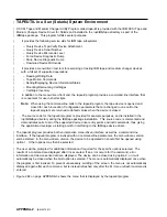
TAPEUTIL in a Windows NT System Environment
|
NT Utility Program
|
The Magstar device is supported on Intel-based processors with a minimum processor level of Intel 486DX
|
or Pentium with sufficient RAM and disk space for operation of the Microsoft Windows NT operating
|
system.
|
The utility has these general characteristics:
|
1. Can be driven interactively or from a file (batch mode).
|
2. Allows specification of desired results from each step of the test so that the test can be self-checking.
|
3. Allows testing of all device driver interfaces with both valid and invalid parameters.
|
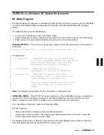
Invoking NTUTIL:
The tool can be invoked as a command from the command line or from within a
|
shell script:
|
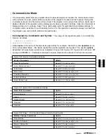
ntutil <-f input-file> <-o output-file> <-d special-file> <-t>
|
The options are:
|
-f input-file
Specifies the input file for batch mode.
|
If a file is specified, NTUTIL will execute in
|
batch mode and read input from this file.
|
The default for this file is NTUTIL.in.
|
-o output-file
Specifies the output file.
|
The default for this file is NTUTIL.out.
|
-d special-file
Specifies the special file value
|
(for example, tape ) to substitute on the
|
"open" statement in the input file.
|
-t
Turns on internal tracing printouts in the
|
output file. Used only to debug the tool
|
itself.
|
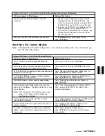
NoteIf no parameters are specified, NTUTIL will operate in interactive mode.
|
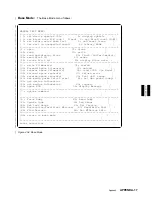
Interactive Mode:
When NTUTIL is invoked without the
-f flag, it defaults to running in interactive or
|
manual mode. This mode allows a developer to interactively determine the kind of testing to be done.
|
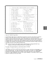
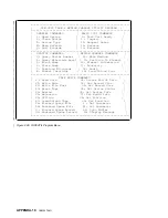
When in interactive mode, NTUTIL provides a menu of functions that can be performed.
|
For a description of interactive modes, see Interactive Mode
|
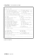
The two modes are:
|
Base mode (LUN0) commands such as open/close/read/write
|
Library mode (LUN0 and LUN1) that supports open/close/read/write plus media mover commands
|
such as read element status and move media.
|
The Magstar 3590 must be in Random 2 LUN mode and the other Magstar devices must be in Random
|
mode both when booted and to operate NTUTIL in library mode.
APPENDA
AppendA
APPENDA-15
Summary of Contents for Magstar MP 3570 C Series
Page 1: ...IBM Magstar MP 3570 Tape Subsystem Maintenance Information C Series Models...
Page 2: ......
Page 12: ...x IBM 3570 MI...
Page 46: ...MAPS 2 IBM 3570 MI...
Page 56: ...Notes MAPS 12 IBM 3570 MI...
Page 62: ...MAPS 18 IBM 3570 MI...
Page 70: ...Notes MAPS 26 IBM 3570 MI...
Page 72: ...MAPS 28 IBM 3570 MI...
Page 84: ...Figure 22 Label Locations for Models Without Libraries INTRO 12 IBM 3570 MI...
Page 87: ...Figure 25 Model C00 Drive INTRO Introduction INTRO 15...
Page 95: ...Figure 29 Model C02 Stand Alone Library Model INTRO Introduction INTRO 23...
Page 96: ...A 2 1 M 0 0 3 5 Figure 30 Model C11 Rack Mounted Library Model INTRO 24 IBM 3570 MI...
Page 97: ...Figure 31 Model C12 Rack Mounted Library Model INTRO Introduction INTRO 25...
Page 98: ...Figure 32 Model C21 Rack Mounted Library Model INTRO 26 IBM 3570 MI...
Page 99: ...Figure 33 Model C22 Rack Mounted Library Model INTRO Introduction INTRO 27...
Page 120: ...INTRO 48 IBM 3570 MI...
Page 136: ...Figure 57 Model C02 Stand Alone Library Model LIBRARY 16 IBM 3570 MI...
Page 137: ...A 2 1 M 0 0 3 5 Figure 58 Model C11 Rack Mounted Library Model LIBRARY Library LIBRARY 17...
Page 138: ...Figure 59 Model C12 Rack Mounted Library Model LIBRARY 18 IBM 3570 MI...
Page 139: ...Figure 60 Model C21 Rack Mounted Library Model LIBRARY Library LIBRARY 19...
Page 144: ...LIBRARY 24 IBM 3570 MI...
Page 192: ...Figure 108 Operator Menus PANEL 12 IBM 3570 MI...
Page 206: ...Figure 128 Part 1 of 3 CE Panel Menu PANEL 26 IBM 3570 MI...
Page 207: ...Figure 128 Part 2 of 3 CE Panel Menu PANEL Operator Panel PANEL 27...
Page 208: ...Figure 128 Part 3 of 3 CE Panel Menu PANEL 28 IBM 3570 MI...
Page 242: ...PANEL 62 IBM 3570 MI...
Page 249: ...Korean Inspection INSP 7...
Page 250: ...Korean INSP 8 IBM 3570 MI...
Page 256: ...Figure 187 Support Slide left side Models C21 and C22 INSP 14 IBM 3570 MI...
Page 260: ...INSP 18 IBM 3570 MI...
Page 270: ...Figure 196 Model C00 Drive Inner Cover Configuration INST 10 IBM 3570 MI...
Page 273: ...Figure 200 Drive Only Model C00 SCSI Connection INST Installation INST 13...
Page 275: ...Figure 202 EIA Rack Template for Models C11 and C12 INST Installation INST 15...
Page 276: ...This Page Left Intentionally Blank INST 16 IBM 3570 MI...
Page 288: ...INST 28 IBM 3570 MI...
Page 289: ...Figure 212 EIA Rack Template for Models C21 and C22 INST Installation INST 29...
Page 290: ...This Page Left Intentionally Blank INST 30 IBM 3570 MI...
Page 297: ...Figure 216 Attaching Cable Arm and Strain Relief Bracket INST Installation INST 37...
Page 312: ...Figure 227 Rear View of Model C02 C12 or C22 INST 52 IBM 3570 MI...
Page 319: ...Figure 237 Cable Routing Model C11 INST Installation INST 59...
Page 321: ...Figure 240 Cable Routing Model C21 INST Installation INST 61...
Page 328: ...INST 68 IBM 3570 MI...
Page 348: ...Figure 252 Removing a Stuck Cartridge From a Drive PROC 20 IBM 3570 MI...
Page 369: ...Figure 260 Blank Error Log Analysis Work Sheet PROC Common Procedures PROC 41...
Page 371: ...Figure 263 Example Error Log Analysis Work Sheet PROC Common Procedures PROC 43...
Page 396: ...6 When the Tape Device Test menu is displayed select Exit test menu 3 PROC 68 IBM 3570 MI...
Page 420: ...PROC 92 IBM 3570 MI...
Page 424: ...Figure 270 Library Model C01 Exploded View CARR 4 IBM 3570 MI...
Page 435: ...Figure 274 Base Drive FRU Breakout CARR Checks Adjustments Removals and Replacements CARR 15...
Page 448: ...Figure 279 Library Front Door Assembly Holding Screws CARR 28 IBM 3570 MI...
Page 456: ...CARR 36 IBM 3570 MI...
Page 504: ...APPENDC 2 IBM 3570 MI...
Page 521: ...APPENDC Appendix C APPENDC 19...
Page 522: ...Notes APPENDC 20 IBM 3570 MI...
Page 532: ...APPENDC 30 IBM 3570 MI...
Page 537: ...Figure 312 Library Model C01 Exploded View APPENDD Appendix D APPENDD 5...
Page 541: ...Figure 315 Basic Drive All Models APPENDD Appendix D APPENDD 9...
Page 546: ...Figure 317 Base Drive FRU Breakout APPENDD 14 IBM 3570 MI...
Page 551: ...Figure 318 Base Drive Head Actuator Assembly Close up APPENDD Appendix D APPENDD 19...
Page 557: ...APPENDD Appendix D APPENDD 25...
Page 563: ...Figure 326 Drive Loader Assembly Exploded View APPENDD Appendix D APPENDD 31...
Page 580: ...Figure 332 Library Front Door Assembly Holding Screws APPENDD 48 IBM 3570 MI...
Page 591: ...Parts Catalog Parts Catalog PARTS 3...
Page 592: ...Assembly 1 Rackmount Library Assembly Model C11 PARTS 4 IBM 3570 MI...
Page 594: ...Assembly 2 Desktop Drive Model C00 PARTS 6 IBM 3570 MI...
Page 596: ...Assembly 3 Desktop Library Assembly Model C01 PARTS 8 IBM 3570 MI...
Page 598: ...Assembly 4 Rackmount Library Assembly Model C12 PARTS 10 IBM 3570 MI...
Page 601: ...Parts Catalog Parts Catalog PARTS 13...
Page 602: ...Assembly 5 Desktop Library Assembly Model C02 PARTS 14 IBM 3570 MI...
Page 605: ...Parts Catalog Parts Catalog PARTS 17...
Page 606: ...Assembly 6 Rackmount Library Assembly Model C21 PARTS 18 IBM 3570 MI...
Page 608: ...Assembly 7 Rackmount Library Assembly Model C22 PARTS 20 IBM 3570 MI...
Page 611: ...Parts Catalog Parts Catalog PARTS 23...
Page 612: ...Assembly 8 Base Drive All Models PARTS 24 IBM 3570 MI...
Page 614: ...PARTS 26 IBM 3570 MI...
Page 629: ...wrap tool SCSI port PROC 77 INDEX Index Index 7...

