


Check to see if the write-protect tab is set in the upward position to protect the tape from being written
on. If you are attempting to write on the tape with the write-protect tab upward, you will experience an
error condition.
Check to ensure that the cartridge is the proper type (Magstar MP Fast Access Linear Tape).
Ensure that a cleaner cartridge has been inserted if one has been requested and, conversely, that no
cleaner cartridge has been inserted if a data cartridge is required.
Check to see if the display indicates FID1 95. If it does, you may have forgotten to remove the
shipping bracket. Remove the bracket and continue the procedure. See steps at “Installation
Checkout—Library Models” on page INST-40.
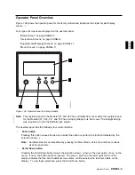
Ensure that the library is in operator mode (see
5
in Figure 104 on page PANEL-3).
Ensure that the library is on-line.
Turn the power off and then on again.
Note: Two power cords are required for Models C02 and C12. Make sure both power cords are plugged
into the library unit and into the power outlet.
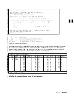
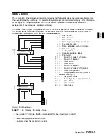
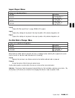
Supplemental Message Screens
Supplemental screens provide additional information to the operator to clarify an error condition or to
advise the operator to follow a particular course of action to resolve specific error conditions.
Generally, it is necessary to press the Enter button after an error message appears to see the
accompanying supplemental screen.
PANEL
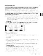
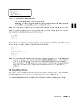
Menu Screens
When a menu screen is present, use the Scroll Down button (see
3
in Figure 104 on page PANEL-3) or
the Scroll Up button (see
4
in Figure 104 on page PANEL-3) to move the arrow (
>
) to the desired
selection, and then press the Enter button (see
2
in Figure 104 on page PANEL-3). This operation will
select the desired option from the menu.
Note: An option marked with an asterisk indicates the option is not available for selection or the option is
the selection currently in use by the library. For example: if the drive is not loaded with a tape cartridge,
the UNLOAD DRIVE option will be marked with an asterisk indicating it is not available for selection.
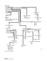
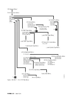
Operator Menus
Figure 108 on page PANEL-12 shows the operator menu functions. (The bold text in the figure shows
the names of the menus.)
These menus are available after the successful completion of the power-on self-test.
Operator Panel
PANEL-11
Summary of Contents for Magstar MP 3570 C Series
Page 1: ...IBM Magstar MP 3570 Tape Subsystem Maintenance Information C Series Models...
Page 2: ......
Page 12: ...x IBM 3570 MI...
Page 46: ...MAPS 2 IBM 3570 MI...
Page 56: ...Notes MAPS 12 IBM 3570 MI...
Page 62: ...MAPS 18 IBM 3570 MI...
Page 70: ...Notes MAPS 26 IBM 3570 MI...
Page 72: ...MAPS 28 IBM 3570 MI...
Page 84: ...Figure 22 Label Locations for Models Without Libraries INTRO 12 IBM 3570 MI...
Page 87: ...Figure 25 Model C00 Drive INTRO Introduction INTRO 15...
Page 95: ...Figure 29 Model C02 Stand Alone Library Model INTRO Introduction INTRO 23...
Page 96: ...A 2 1 M 0 0 3 5 Figure 30 Model C11 Rack Mounted Library Model INTRO 24 IBM 3570 MI...
Page 97: ...Figure 31 Model C12 Rack Mounted Library Model INTRO Introduction INTRO 25...
Page 98: ...Figure 32 Model C21 Rack Mounted Library Model INTRO 26 IBM 3570 MI...
Page 99: ...Figure 33 Model C22 Rack Mounted Library Model INTRO Introduction INTRO 27...
Page 120: ...INTRO 48 IBM 3570 MI...
Page 136: ...Figure 57 Model C02 Stand Alone Library Model LIBRARY 16 IBM 3570 MI...
Page 137: ...A 2 1 M 0 0 3 5 Figure 58 Model C11 Rack Mounted Library Model LIBRARY Library LIBRARY 17...
Page 138: ...Figure 59 Model C12 Rack Mounted Library Model LIBRARY 18 IBM 3570 MI...
Page 139: ...Figure 60 Model C21 Rack Mounted Library Model LIBRARY Library LIBRARY 19...
Page 144: ...LIBRARY 24 IBM 3570 MI...
Page 192: ...Figure 108 Operator Menus PANEL 12 IBM 3570 MI...
Page 206: ...Figure 128 Part 1 of 3 CE Panel Menu PANEL 26 IBM 3570 MI...
Page 207: ...Figure 128 Part 2 of 3 CE Panel Menu PANEL Operator Panel PANEL 27...
Page 208: ...Figure 128 Part 3 of 3 CE Panel Menu PANEL 28 IBM 3570 MI...
Page 242: ...PANEL 62 IBM 3570 MI...
Page 249: ...Korean Inspection INSP 7...
Page 250: ...Korean INSP 8 IBM 3570 MI...
Page 256: ...Figure 187 Support Slide left side Models C21 and C22 INSP 14 IBM 3570 MI...
Page 260: ...INSP 18 IBM 3570 MI...
Page 270: ...Figure 196 Model C00 Drive Inner Cover Configuration INST 10 IBM 3570 MI...
Page 273: ...Figure 200 Drive Only Model C00 SCSI Connection INST Installation INST 13...
Page 275: ...Figure 202 EIA Rack Template for Models C11 and C12 INST Installation INST 15...
Page 276: ...This Page Left Intentionally Blank INST 16 IBM 3570 MI...
Page 288: ...INST 28 IBM 3570 MI...
Page 289: ...Figure 212 EIA Rack Template for Models C21 and C22 INST Installation INST 29...
Page 290: ...This Page Left Intentionally Blank INST 30 IBM 3570 MI...
Page 297: ...Figure 216 Attaching Cable Arm and Strain Relief Bracket INST Installation INST 37...
Page 312: ...Figure 227 Rear View of Model C02 C12 or C22 INST 52 IBM 3570 MI...
Page 319: ...Figure 237 Cable Routing Model C11 INST Installation INST 59...
Page 321: ...Figure 240 Cable Routing Model C21 INST Installation INST 61...
Page 328: ...INST 68 IBM 3570 MI...
Page 348: ...Figure 252 Removing a Stuck Cartridge From a Drive PROC 20 IBM 3570 MI...
Page 369: ...Figure 260 Blank Error Log Analysis Work Sheet PROC Common Procedures PROC 41...
Page 371: ...Figure 263 Example Error Log Analysis Work Sheet PROC Common Procedures PROC 43...
Page 396: ...6 When the Tape Device Test menu is displayed select Exit test menu 3 PROC 68 IBM 3570 MI...
Page 420: ...PROC 92 IBM 3570 MI...
Page 424: ...Figure 270 Library Model C01 Exploded View CARR 4 IBM 3570 MI...
Page 435: ...Figure 274 Base Drive FRU Breakout CARR Checks Adjustments Removals and Replacements CARR 15...
Page 448: ...Figure 279 Library Front Door Assembly Holding Screws CARR 28 IBM 3570 MI...
Page 456: ...CARR 36 IBM 3570 MI...
Page 504: ...APPENDC 2 IBM 3570 MI...
Page 521: ...APPENDC Appendix C APPENDC 19...
Page 522: ...Notes APPENDC 20 IBM 3570 MI...
Page 532: ...APPENDC 30 IBM 3570 MI...
Page 537: ...Figure 312 Library Model C01 Exploded View APPENDD Appendix D APPENDD 5...
Page 541: ...Figure 315 Basic Drive All Models APPENDD Appendix D APPENDD 9...
Page 546: ...Figure 317 Base Drive FRU Breakout APPENDD 14 IBM 3570 MI...
Page 551: ...Figure 318 Base Drive Head Actuator Assembly Close up APPENDD Appendix D APPENDD 19...
Page 557: ...APPENDD Appendix D APPENDD 25...
Page 563: ...Figure 326 Drive Loader Assembly Exploded View APPENDD Appendix D APPENDD 31...
Page 580: ...Figure 332 Library Front Door Assembly Holding Screws APPENDD 48 IBM 3570 MI...
Page 591: ...Parts Catalog Parts Catalog PARTS 3...
Page 592: ...Assembly 1 Rackmount Library Assembly Model C11 PARTS 4 IBM 3570 MI...
Page 594: ...Assembly 2 Desktop Drive Model C00 PARTS 6 IBM 3570 MI...
Page 596: ...Assembly 3 Desktop Library Assembly Model C01 PARTS 8 IBM 3570 MI...
Page 598: ...Assembly 4 Rackmount Library Assembly Model C12 PARTS 10 IBM 3570 MI...
Page 601: ...Parts Catalog Parts Catalog PARTS 13...
Page 602: ...Assembly 5 Desktop Library Assembly Model C02 PARTS 14 IBM 3570 MI...
Page 605: ...Parts Catalog Parts Catalog PARTS 17...
Page 606: ...Assembly 6 Rackmount Library Assembly Model C21 PARTS 18 IBM 3570 MI...
Page 608: ...Assembly 7 Rackmount Library Assembly Model C22 PARTS 20 IBM 3570 MI...
Page 611: ...Parts Catalog Parts Catalog PARTS 23...
Page 612: ...Assembly 8 Base Drive All Models PARTS 24 IBM 3570 MI...
Page 614: ...PARTS 26 IBM 3570 MI...
Page 629: ...wrap tool SCSI port PROC 77 INDEX Index Index 7...


