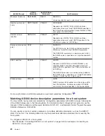
AS/400 Prompt
AS/400
Parameter
Remote AS/400
Parameter
Notes
Connection initiation
CNNINIT
CNNINIT
If X.25 DCE support is specified (X25DCE(*YES)) for
either system, CNNINIT(*LOCAL) should also be
specified on that system’s line description. The other
system (with X25DCE(*NO) specified) should specify
CNNINIT(*REMOTE) or CNNINIT(*WAIT).
For switched connections, both systems can also
specify X25DCE(*NEG) to negotiate the Distributed
Computing Environment (DCE) and data terminal
equipment (DTE) roles and CNNINIT(*CALLER) to allow
either system to initiate the connection by making the
call.
See the X25DCE parameter for additional
considerations.
Duplex
DUPLEX
DUPLEX
Depending on the type of communications used, the
values specified for the DUPLEX parameters may need
to be coordinated.
Ethernet standard
ETHSTD
ETHSTD
Values specified for each system must be coordinated.
Both systems must specify the same standard (*ETHV2
or *IEEE8023) or at least one system must specify
*ALL.
Exchange identifier
EXCHID
EXCHID
Remote AS/400 controller description EXCHID must
match the local AS/400 line description EXCHID. The
first three digits of the exchange identifier, known as the
block number, is
056
for the AS/400 line. You can use
the Work with Line Descriptions (WRKLIND) command
to determine this value.
Logical channel
entries
LGLCHLE
LGLCHLE
If X.25 DCE support is specified (X25DCE(*YES) or
X25DCE(*NEG)), logical channel types and channel
numbers must be coordinated. See also the
considerations for the X25DCE parameter.
Line speed
LINESPEED
LINESPEED
For asynchronous lines, the line speeds specified for
each system must match.
Modulus
MODULUS
MODULUS
If X.25 DCE support is specified (X25DCE(*YES) or
X25DCE(*NEG)), modulus values specified for each
system must match.
The values specified for this parameter should match for
all communications types.
Local network address NETADR
CNNNBR
For switched virtual circuits (SVCs), the NETADR
parameter on the local system line description must
match the CNNNBR parameter on the
controller
description
for the remote system.
NRZI data encoding
NRZI
NRZI
Values specified for each system must match (*YES or
*NO).
Data link role
ROLE
ROLE
The value specified for the local system line description
ROLE parameter should match the controller description
ROLE parameter specified at the remote system.
Number of stop bits
STOPBITS
STOPBITS
Values specified for each system must match.
Switched connection
type
SWTCNN
SWTCNN
Values specified for each system must be compatible.
(*DIAL or *ANS must not be specified for
both
systems.)
34
Version 5
Summary of Contents for AS/400
Page 1: ...iSeries Networking iSeries Communications Management ERserver...
Page 2: ......
Page 3: ...iSeries Networking iSeries Communications Management ERserver...
Page 8: ...2 Version 5...
Page 10: ...4 Version 5...
Page 12: ...6 Version 5...
Page 22: ...For more information about creating subsystems see the Work Management book 16 Version 5...
Page 26: ...20 Version 5...
Page 34: ...Example 3 AS 400 system for DLUR support with the host system 28 Version 5...
Page 36: ...30 Version 5...
Page 46: ...40 Version 5...
Page 57: ...Chapter 7 Communicating with remote workstation controllers 51...
Page 63: ...Chapter 7 Communicating with remote workstation controllers 57...
Page 82: ...Example 2 AS 400 to 4690 PEER connection over token ring network 76 Version 5...
Page 83: ...Chapter 7 Communicating with remote workstation controllers 77...
Page 84: ...78 Version 5...
Page 102: ...96 Version 5...
Page 103: ......
Page 104: ...Printed in U S A...


