background image

v

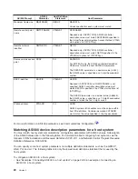
Use the following table for the device description parameter.

AS/400 Prompt

AS/400

Parameter

Host Definition

Statement

Host Parameter

Local location name

LCLLOCNAME

DFHTCT

NETNAME

AS/400 LCLLOCNAME value must match CICS/VS
terminal control table NETNAME parameter and the
label used on the LU definition statement.

Local location address LOCADR

LU

LOCADDR

Values specified for each system must match.

The LOCADDR parameter is a decimal value (0-255);
the AS/400 value is specified as a 2-digit hexadecimal
number.

Location password

LOCPWD

DFHTCT

BINDPWD

Values specified for each system must match.

Dependent location
name

DEPLOCNAME

LU

LU

This parameter is only used for DLUR support. This
value is optional. If specified, it must match LUNAME
received on ACTLUREQUEST.

Mode description
name

MODE

MODEENT

LOGMODE

AS/400 mode description name must be defined in the
host logon mode table using the LOGMODE parameter
on the MODEENT macro instruction. The mode name
must also be included in the CICS/VS terminal control
table (DFHTCT) MODENAM parameter.

Remote location name RMTLOCNAME

LU

LOGAPPL

Values specified for each system must match.

Remote network
identifier

RMTNETID

BUILD

NETID

Values specified for each system must match.

For more information on AS/400 parameters, see Communications Configuration.

Matching AS/400 mode and class-of-service description parameters for
a host system

You must match host system communications configuration parameters with AS/400 values. A description
of the AS/400 values are in the following table. For information about configuring host systems, see the
manuals

VTAM Installation and Resource Definition

, SC23-0111, and

Network Control Program Resource

Definition Reference

, SC30-3254.

You can specify some host system parameters on multiple definition statements, such as the GROUP,
LINE, PU, and LU. The following table lists only the lowest level definition statement that is used by the
host system.

To configure an AS/400 to a host system:

v

See “Examples: Connecting AS/400 to a host system” on page 26 for an example of connecting an
AS/400 to a host system.

v

Use the following table for the mode and class-of-service description parameter.

Chapter 5. Communicating with host systems

25

Summary of Contents for AS/400

Page 1: ...iSeries Networking iSeries Communications Management ERserver...

Page 2: ......

Page 3: ...iSeries Networking iSeries Communications Management ERserver...

Page 4: ...pyright International Business Machines Corporation 1998 2001 All rights reserved US Government Users Restricted Rights Use duplication or disclosure restricted by GSA ADP Schedule Contract with IBM C...

Page 5: ...ata management DDM 17 Application program interface API performance considerations 17 Performance considerations for intersystem communications function 18 Performance considerations for Common Progra...

Page 6: ...the Print Error Log to solve communication problems 80 Job logs and communication problems 80 Solving communication problems using communications trace 81 System service tools and communication probl...

Page 7: ...ronment review the topics Optimizing communications performance and Communications applications You can configure your AS 400 system to communicate with another AS 400 system a non AS 400 system or a...

Page 8: ...2 Version 5...

Page 9: ...r printing 1 Open the PDF in your browser click the link above 2 In the menu of your browser click File 3 Click Save As 4 Navigate to the directory in which you would like to save the PDF 5 Click Save...

Page 10: ...4 Version 5...

Page 11: ...description A network server description describes which Integrated PC Server the local area network LAN and the application will be using To create a network server description do the following 1 Ty...

Page 12: ...6 Version 5...

Page 13: ...MAXFRAME parameters to their maximum value v Configure a WAN line as full duplex to provide you with a higher throughput for applications that can take advantage of this mode This can also provide hi...

Page 14: ...eads Communications input output processor resource is also used to support the line activity v When a single job is running disk operations or doing non overlapped CPU processing the communications l...

Page 15: ...line types This is due to the desirable combination of having a high media speed along with large frame sizes v When several sessions use a line or LAN concurrently the aggregate data rate may be high...

Page 16: ...with communications lines and local area networks LANs you should not overload an input output processor IOP to prevent possible system performance bottlenecks The following information can help you...

Page 17: ...ystems v The work that is performed in the QCMN subsystem is for connecting and disconnecting from the system Error recovery considerations are important in the configuration of the communications sub...

Page 18: ...Telnet are some examples of these types of connections that should be separated When you configure interactive subsystems identify how you want the interactive users to be separated and create the app...

Page 19: ...ptimize batch jobs for communications consider the following v Break the application into pieces and having multiple batch threads jobs operate concurrently v Reduce the number of open and close opera...

Page 20: ...rmation about AnyNet 400 sockets see the book Sockets Programming Setting up the AnyNet environment AnyNet 400 is an AnyNet family product These products allow you to use application programs that are...

Page 21: ...ion address A TCP IP domain name server converts these location names to IP addresses Programs supported include distributed data management DDM Distributed Relational Database Architecture DRDA SNA d...

Page 22: ...For more information about creating subsystems see the Work Management book 16 Version 5...

Page 23: ...of the following routing functions v Non adjacent nodes appear adjacent and so APPC programs may communicate directly to programs in non adjacent nodes without any APPC programs on the intermediate n...

Page 24: ...ion ICF to write application programs that you want to communicate with advanced program to program communications APPC ICF also provides program to device communications between the AS 400 system and...

Page 25: ...rograms do the following v Minimize the use of flush and confirm v Receive a compile record and parse it in your buffer v Do not use multiple receive calls to receive a single record v Use Request to...

Page 26: ...20 Version 5...

Page 27: ...e Definition SC23 0111 and Network Control Program Resource Definition Reference SC30 3254 v Matching AS 400 line description parameters for a host system v Matching AS 400 controller description para...

Page 28: ...specified for the host system if CNN is MP or NONSWTPP DIAL NO must be specified If CNN MP is specified the SERVICE macroinstruction must be used to specify the sequence in which stations are served...

Page 29: ...h is required if AS 400 host controller description specifies RMTCPNAME ANY SWITCHED YES or SNBU YES and LINKTYPE is SDLC or IDLC This parameter should be specified only if the host system is running...

Page 30: ...ATCSTRyy The SSCPID parameter is a decimal value 0 65535 the AS 400 value is specified as a 12 digit hexadecimal number of which the first 2 digits are 05 Station address STNADR PU ADDR AS 400 system...

Page 31: ...ontrol table DFHTCT MODENAM parameter Remote location name RMTLOCNAME LU LOGAPPL Values specified for each system must match Remote network identifier RMTNETID BUILD NETID Values specified for each sy...

Page 32: ...on the AS 400 Create Class of Service Description CRTCOSD command COSD parameter and CRTMODD command COS parameter must be defined in the host logon mode table using the COS parameter on the MODEENT...

Page 33: ...xample 2 AS 400 to host system over a token ring line This diagram shows the AS 400 values that need to match the VTAM values when you use a token ring line Chapter 5 Communicating with host systems 2...

Page 34: ...Example 3 AS 400 system for DLUR support with the host system 28 Version 5...

Page 35: ...o match the VTAM values when you use AS 400 DLUR and VTAM Example 4 AS 400 with APPN connection to VTAM This diagram shows the AS 400 values that need to match the VTAM values when you connect with AP...

Page 36: ...30 Version 5...

Page 37: ...ster DLUR controller description using the Retrieve Configuration Source RTVCFGSRC command 2 Edit the member to change the link type to DLUR 3 Convert the source to a CL program 4 Create the CL progra...

Page 38: ...Note This must match the VTAM LU name with the corresponding local location address LOCADDR on VTAM For more information on DLUR see Dependent LU Requester Support DLUR 32 Version 5...

Page 39: ...remote AS 400 system You must coordinate communications configuration parameters between local and remote AS 400 systems These parameters are described in the following table This table shows those p...

Page 40: ...056 for the AS 400 line You can use the Work with Line Descriptions WRKLIND command to determine this value Logical channel entries LGLCHLE LGLCHLE If X 25 DCE support is specified X25DCE YES or X25DC...

Page 41: ...al and remote AS 400 systems To configure a local AS 400 to a remote AS 400 v See Connecting one AS 400 to another AS 400 system on page 37 for an example of connecting one AS 400 to another AS 400 sy...

Page 42: ...ystem must be coordinated Switched network backup SNBU SNBU Values specified for each system must match Source service access point SSAP DSAP SSAP specified for the local AS 400 system must match the...

Page 43: ...description Remote location name RMTLOCNAME LCLLOCNAME For systems not using APPN APPN NO specified for the controller and device descriptions this value must match the value specified by the LCLLOCN...

Page 44: ...This example shows the matching parameters between an AS 400 connecting to another AS 400 that uses X 25 Example 2 AS 400 to AS 400 using SDLC 38 Version 5...

Page 45: ...another AS 400 that uses SDLC Example 3 AS 400 to AS 400 using one way automatic dialing This example shows the matching parameters between an AS 400 connecting to another AS 400 that uses one way aut...

Page 46: ...40 Version 5...

Page 47: ...Ethernet on page 44 Matching AS 400 parameters for a 5494 connected by frame relay on page 46 Matching AS 400 parameters for a 5494 connected by SDLC on page 48 Matching AS 400 parameters for a 5494...

Page 48: ...LOCNAME H1 1 Values specified for the AS 400 CRTCTLRWS command and for the 5494 Remote Control Unit must match This will probably match LCLLOCNAME in the network attributes This value will probably ma...

Page 49: ...5494 configuration must be compatible with the physical interface INTERFACE parameter specified on the CRTLINSDLC command Select 4 for the network connections Example Connecting AS 400 to a 5494 contr...

Page 50: ...er that is connected by Ethernet A description of these parameters are in the following table Then the related fields and subfields from the 5494 configuration display and the AS 400 configuration val...

Page 51: ...cal location name LCLLOCNAME H1 1 Values specified for the AS 400 CRTCTLRWS command and for the 5494 Remote Control Unit must match This will probably match LCLLOCNAME in the network attributes This v...

Page 52: ...can coordinate these values automatically or manually Pick one of these ways v To automatically connect the AS 400 to a 5494 controller you can use the automatic remote controller QAUTORMT system valu...

Page 53: ...ecified for the LINKTYPE parameter on the CRTCTLAPPC command For APPC controllers that specify LINKTYPE SDLC the value specified in the 5494 configuration must be compatible with the physical interfac...

Page 54: ...re listed next These values are followed by the AS 400 configuration value and the matching 5494 value to be entered in the display subfield You can coordinate these values automatically or manually P...

Page 55: ...k attributes Link type LINKTYPE AA SDLC 0 2 3 5494 configuration values must match the values specified for the LINKTYPE parameter on the CRTCTLAPPC command For APPC controllers that specify LINKTYPE...

Page 56: ...in the AS 400 controller description and for the 5494 Remote Control Unit must match This value must also be specified as the last 2 digits of the AS 400 EXCHID parameter Example Connecting AS 400 to...

Page 57: ...Chapter 7 Communicating with remote workstation controllers 51...

Page 58: ...5494 Remote Control Unit Planning Guide GA27 3936 v IBM 5494 Remote Control Unit User s Guide GA27 3852 AS 400 Prompt AS 400 Parameter 5494 AS 400 Value 5494 Value Notes Field Subfield Connection numb...

Page 59: ...the AS 400 controller description and for the 5494 Remote Control Unit must match This value must also be specified as the last 2 digits of the AS 400 EXCHID parameter Example Connecting AS 400 to a 5...

Page 60: ...lay subfield You can coordinate these values automatically or manually Pick one of these ways v To automatically connect the AS 400 to a 5494 controller you can use the automatic remote controller QAU...

Page 61: ...rs that specify LINKTYPE SDLC the value specified in the 5494 configuration must be compatible with the physical interface INTERFACE parameter specified on the CRTLINSDLC command Select 1 for communic...

Page 62: ...ol Unit must match This value must also be specified as the last 2 digits of the AS 400 EXCHID parameter Example Connecting AS 400 to a 5494 controller connected by X 25 Configuration parameters must...

Page 63: ...Chapter 7 Communicating with remote workstation controllers 57...

Page 64: ...Ethernet support To configure the AS 400 to a 3174 controller v See Example Connecting an AS 400 to a 3174 control unit on page 61 for an example of connecting an AS 400 to a 3174 retail controller v...

Page 65: ...25 SVCs the connection number specified on the CRTCTLRWS command and in question 424 must match Destination service access point DSAP 940 Ring Address Assignment The value specified for the DSAP param...

Page 66: ...n 104 must match the STNADR specified on the CRTCTLRWS command Switched connection SWITCHED 317 Telecommunication Facilities Values specified on the CRTLINSDLC command and in question 317 match as fol...

Page 67: ...HNAD For X 25 SVCs the network address specified on the CRTLINX25 command and in sequence number 410 must match Modem data rate select MODEMRATE 318 Full or Half Speed Transmission The values specifi...

Page 68: ...70x finance controllers You must match the AS 400 configuration parameters with the configuration CPGEN for the 4701 and 4702 finance controllers These parameters are described in the following table...

Page 69: ...ications the LLC parameter must specify QLLC for the type of logical link control LINKPCL QLLC must also be specified on the AS 400 CRTCTLFNC command Link type LINKTYPE COMLINK TYPE 4700 TYPE paramete...

Page 70: ...address STNADR X25CKT CUA The values specified for the AS 400 STNADR parameter on the CRTCTLFNC command must match the physical address CUA parameter specified for the 4700 Matching AS 400 parameters...

Page 71: ...iderations in the Communications Configuration book Connection type CNN SDLC Communications Switched line Values specified for the FBSS and AS 400 configurations must match v If the FBSS response is Y...

Page 72: ...parameter value specified on the CRTDEVFNC command The FBSS logical unit assignments are decimal numbers the AS 400 values must be hexadecimal LU Assignments for Display Emulators LU Assignments for...

Page 73: ...AS 400 system and in the controller configuration For an example on connecting an AS 400 to a 4690 retail controller see Examples Connecting AS 400 to a 4690 retail controller on page 75 To match par...

Page 74: ...e Store System Language and Host Services Macro Reference To configure the AS 400 to a 3651 retail controller use the following table AS 400 Prompt AS 400 Parameter 3651 Definition Statement 3651 Para...

Page 75: ...describes how to coordinate values for parameters on the AS 400 CRTLINSDLC and CRTCTLRTL commands with bits that are specified for the 3651 SDLCLIN parameter The SDLCLIN parameter is specified as a se...

Page 76: ...rates the answer tone or 1 to indicate that the controller generates the answer tone 1 None For information about SDLC see Synchronous data link control network on page 94 Matching AS 400 parameters f...

Page 77: ...D parameter specified on the AS 400 CRTCTLRTL command Station address STNADR QVSFGLNK POLCHAR 3684 POLCHAR parameter must match the 2 digit hexadecimal address specified for the STNADR parameter on th...

Page 78: ...network backup 1 SNBU YES 5 0 MODEMRATE FULL Data rate select speed 1 MODEMRATE HALF 6 0 DUPLEX HALF Data carrier setting 1 DUPLEX FULL 7 0 None Answer tone generation There is no equivalent parameter...

Page 79: ...meter specified on the AS 400 CRTLINSDLC command NRZI data encoding NRZI 4680 NRZI MODE parameter must match the NRZI parameter specified on the AS 400 CRTLINSDLC command Station address STNADR 4680 S...

Page 80: ...er v See Examples Connecting AS 400 to a 4690 retail controller on page 75 for an example of an AS 400 connecting to a 4690 retail controller v Use the following table to connect to a 4690 retail cont...

Page 81: ...CRTLINSDLC command and the RIPSS configuration must match v If the RIPSS response is NRZI NRZI YES must be specified for the CRTLINSDLC command v If the RIPSS response is NRZ NRZI NO must be specifie...

Page 82: ...Example 2 AS 400 to 4690 PEER connection over token ring network 76 Version 5...

Page 83: ...Chapter 7 Communicating with remote workstation controllers 77...

Page 84: ...78 Version 5...

Page 85: ...solve communication problems Message queues receive some messages that are related to communications failures The message lists possible causes of the problem and additional information depending on t...

Page 86: ...ed QPCSMPRT or in a specified output file 2 Find and read these error logs For more information about displaying the Print Error Log see the Communications Management book A variety of job logs may co...

Page 87: ...RC End Communications Trace The ENDCMNTRC command ends the trace currently running on the specified line network interface description or network server description The ENDCMNTRC command saves the com...

Page 88: ...b is active to find out where the error might have occurred The TRCCPIC command captures information about CPI Communications calls that is processed by your program The system collects trace informat...

Page 89: ...lue that is specified on the Trace full prompt If the trace storage area becomes full and the collection of trace records stops you must enter the TRCCPIC command again to create output The output tha...

Page 90: ...stem based on this value Automatic adjustment may be a desirable feature particularly when unexpected loads hit the system Automatic adjustment can help the system perform better through these peak lo...

Page 91: ...fined size is zero 602 Transaction program name value is reserved but not supported 604 Matching routing entry was not found 605 Program was not found 704 Password is not valid 705 User is not authori...

Page 92: ...to current library 1509 Not authorized to QS36PRC in current library 1510 Not authorized to procedure in current library 1511 Not authorized to System 36 environment library 1512 Not authorized to fi...

Page 93: ...be any of the following systems v AS 400 system v System 36 v System 38 v IBM personal computer v Displaywriter v Series 1 v 5520 Administrative System v RISC System 600 Reduced Instruction Set Compu...

Page 94: ...gramming Interface CPI Communications call interface Using CPI Communication calls carries the LU 6 2 verbs v The CICS file interface In CICS 400 support the LU 6 2 verbs are carried out by using EXEC...

Page 95: ...se architecture or can operate under the base architecture plus options There are performance capabilities available under the Tower RTP option not available with the base The page HPR architecture op...

Page 96: ...formation units through networks SNA also controls the configuration and operation of networks APPC APPN and HPR are some examples of the protocols included within SNA They can be used to connect the...

Page 97: ...onous transfer mode ATM network interface NWI describes everything that is common across the ATM physical interface Each AS 400 ATM input output adapter 2809 or 2810 may have one network interface att...

Page 98: ...usually in a star wired ring topology to a wiring concentrator such as the IBM 8228 Multistation Access Unit The concentrator serves as a logical ring around which data is transmitted at 4 million or...

Page 99: ...s support allows you to send data to and receive data from a remote program or device attached by either an asynchronous start stop or an X 25 line Your application program must provide the data strea...

Page 100: ...switching X 31 For more information on ISDN see the topics ISDN on AS 400 and ISDN data link control network ISDN data link control network You can use ISDN data link control IDLC to connect two syste...

Page 101: ...SNA sessions that can include Advanced Program to Program communications APPC SNA upline facility remote work stations or finance communications v One connection to an asynchronous communications hos...

Page 102: ...96 Version 5...

Page 103: ......

Page 104: ...Printed in U S A...

Reviews: