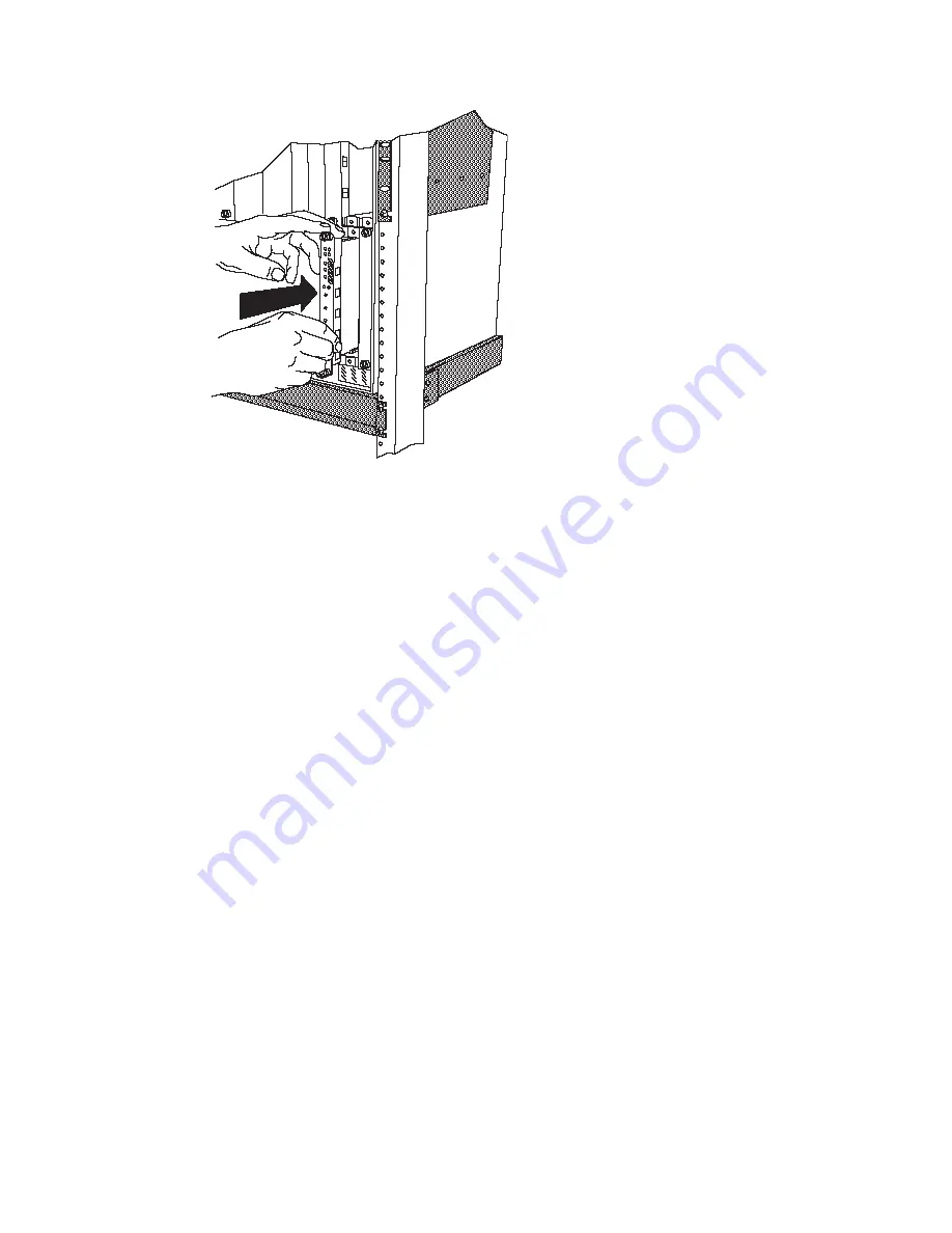
Slide the Controller
Module into the
selected slots as
shown here.
Figure 16. Installing a Controller Module
5. Lock the ejector into place by applying pressure to the Controller module faceplate with one hand as
you pull up on the end of the ejector. Ensure that the Controller module remains fully seated in the
backplane connector as you close the Controller module ejector.
6. Lift the end of the ejector until the ejector locks into place.
7. Complete the installation by hand-turning each of the spring-loaded screws at the top and bottom of
the module in a clockwise direction. Do not overtighten the screws.
8. If you are using the Controller module(s) in conjunction with the CPSW2 module(s), make sure that
the FORCE RCTL jumper on the CPSW2 module is set to the ON position (on both CPSW2 modules
if two are installed).
Attention: To ensure adequate cooling airflow, install blank slot cover plates over
all empty slots.
34
IBM 8265: Installation Guide
Summary of Contents for 8265 Nways ATM Switch
Page 1: ...8265 Nways ATM Switch IBM Installation Guide SA33 0441 02...
Page 2: ......
Page 3: ...8265 Nways ATM Switch IBM Installation Guide SA33 0441 02...
Page 8: ...vi IBM 8265 Installation Guide...
Page 10: ...viii IBM 8265 Installation Guide...
Page 12: ...x IBM 8265 Installation Guide...
Page 14: ...xii IBM 8265 Installation Guide...
Page 32: ...18 IBM 8265 Installation Guide...
Page 52: ...38 IBM 8265 Installation Guide...
Page 68: ...54 IBM 8265 Installation Guide...
Page 88: ...Models 17S Serial Number Located on the 8265 chassis label 74 IBM 8265 Installation Guide...
Page 98: ......
Page 101: ......
Page 102: ...IBM SA33 441 2...


