5.
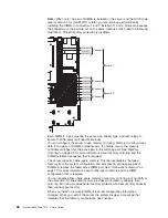
To
attach
peripheral
devices
and
connect
the
power
cords,
see
“Connecting
the
cables.”
Attention:
In
a
dc
power
environment,
only
trained
service
personnel
other
than
IBM
service
technicians
are
authorized
to
connect
or
disconnect
power
to
the
dc
power
supply.
See
the
documentation
that
comes
with
each
dc
power
supply.
Installing
the
cover
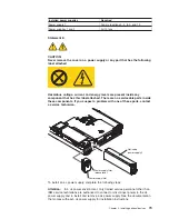
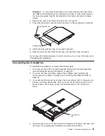
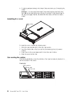
Cover-release
latch
To
install
the
cover,
complete
the
following
steps:
1.
Place
the
cover-release
latch
in
the
open
(up)
position.
2.
Insert
the
bottom
tabs
of
the
top
cover
into
the
matching
slots
in
the
server
chassis.
3.
Press
down
on
the
cover-release
latch
to
lock
the
cover
in
place.
4.
Slide
the
server
into
the
rack.
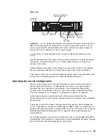
Connecting
the
cables
The
following
illustrations
show
the
locations
of
the
input
and
output
connectors
on
the
front
and
rear
of
the
server.
Front
view
USB 5 connector
USB 6 connector
Video connector
82
System
x3650
Type
7979:
User’s
Guide
Summary of Contents for 7979B1U
Page 1: ...System x3650 Type 7979 User s Guide...
Page 2: ......
Page 3: ...System x3650 Type 7979 User s Guide...
Page 8: ...vi System x3650 Type 7979 User s Guide...
Page 30: ...14 System x3650 Type 7979 User s Guide...
Page 130: ...114 System x3650 Type 7979 User s Guide...
Page 138: ...122 System x3650 Type 7979 User s Guide...
Page 143: ......
Page 144: ...Part Number 44R5189 Printed in USA 1P P N 44R5189...

