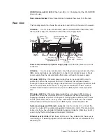
Ethernet
link
LEDs:
When
these
LEDs
are
lit,
they
indicate
that
there
is
an
active
link
connection
on
the
10BASE-T,
100BASE-TX,
or
1000BASE-TX
interface
for
the
Ethernet
port.
Ethernet
connectors:
Use
either
of
these
connectors
to
connect
the
server
to
a
network.
USB
connectors:
Connect
a
USB
device,
such
as
USB
mouse,
keyboard,
or
other
USB
device,
to
any
of
these
connectors.
Video
connector:
Connect
a
monitor
to
this
connector.
The
video
connectors
on
the
front
and
rear
of
the
server
can
be
used
simultaneously.
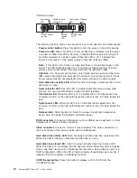
System-error
LED:
When
this
LED
is
lit,
it
indicates
that
a
system
error
has
occurred.
An
LED
on
the
light
path
diagnostics
panel
is
also
lit
to
help
isolate
the
error.
System-locator
LED:
Use
this
LED
to
visually
locate
the
server
among
other
servers.
You
can
use
IBM
Director
to
light
this
LED
remotely.
Power-on
LED:
When
this
LED
is
lit
and
not
flashing,
it
indicates
that
the
server
is
turned
on.
When
this
LED
is
flashing,
it
indicates
that
the
server
is
turned
off
and
still
connected
to
a
power
source.
When
this
LED
is
off,
it
indicates
that
power
is
not
present,
or
the
power
supply
or
the
LED
itself
has
failed.
Serial
connector:
Connect
a
9-pin
serial
device
to
this
connector.
The
serial
port
is
shared
with
the
baseboard
management
controller
(BMC).
The
BMC
can
take
control
of
the
shared
serial
port
to
perform
text
console
redirection
and
to
redirect
serial
traffic,
using
Serial
over
LAN
(SOL).
SAS
connector:
Connect
a
serial-attached
SCSI
(SAS)
device
to
this
connector.
Server
power
features
When
the
server
is
connected
to
a
power
source
but
is
not
turned
on,
the
operating
system
does
not
run,
and
all
core
logic
except
for
the
service
processor
(the
baseboard
management
controller
or
optional
Remote
Supervisor
Adapter
II
SlimLine)
is
shut
down;
however,
the
server
can
respond
to
requests
from
the
service
processor,
such
as
a
remote
request
to
turn
on
the
server.
The
power-on
LED
flashes
to
indicate
that
the
server
is
connected
to
power
but
is
not
turned
on.
Turning
on
the
server
Approximately
5
seconds
after
the
server
is
connected
to
power,
the
power-control
button
becomes
active,
and
one
or
more
fans
might
start
running
to
provide
cooling
while
the
server
is
connected
to
power.
You
can
turn
on
the
server
and
start
the
operating
system
by
pressing
the
power-control
button.
The
server
can
also
be
turned
on
in
any
of
the
following
ways:
v
If
a
power
failure
occurs
while
the
server
is
turned
on,
the
server
will
restart
automatically
when
power
is
restored.
v
If
your
operating
system
supports
the
Wake
on
LAN
feature,
the
Wake
on
LAN
feature
can
turn
on
the
server.
Note:
When
4
GB
or
more
of
memory
(physical
or
logical)
is
installed,
some
memory
is
reserved
for
various
system
resources
and
is
unavailable
to
the
12
System
x3650
Type
7979:
User’s
Guide
Summary of Contents for 7979B1U
Page 1: ...System x3650 Type 7979 User s Guide...
Page 2: ......
Page 3: ...System x3650 Type 7979 User s Guide...
Page 8: ...vi System x3650 Type 7979 User s Guide...
Page 30: ...14 System x3650 Type 7979 User s Guide...
Page 130: ...114 System x3650 Type 7979 User s Guide...
Page 138: ...122 System x3650 Type 7979 User s Guide...
Page 143: ......
Page 144: ...Part Number 44R5189 Printed in USA 1P P N 44R5189...

