


Removal and Replacement
4-71
Lateral Planar 2 Card
Attention: After the lateral planar 2 card is installed and the system is powered–up, the
system ID is down-loaded to the lateral planar 2 card from a backup source within the
system. This ID becomes permanent on the lateral planar 2 and cannot be altered without
special tools. Therefore, the lateral planar 2 cannot be transferred to another system. It
must be returned to the plant of manufacture as a new defective part.
Attention: Lateral planar 2 and SIB EEPROMs contain the SYSID of the system. When
one of the two components is to be replaced (for example the lateral planar 2), the SYSID
information is copied from SIB EEPROM into the lateral planar 2 EEPROM when you start
the system.
To avoid loosing this information, it is not possible to replace both components at the same
time.
When both components are to be replaced, proceed as follows:
1. First substitute the SIB and start up the system: the SYSID information is copied from
lateral planar 2 EEPROM to the SIB EEPROM.
2. Substitute the lateral planar 2 and start up the system: the SYSID information is copied
from SIB EEPROM to the lateral planar 2 EEPROM.
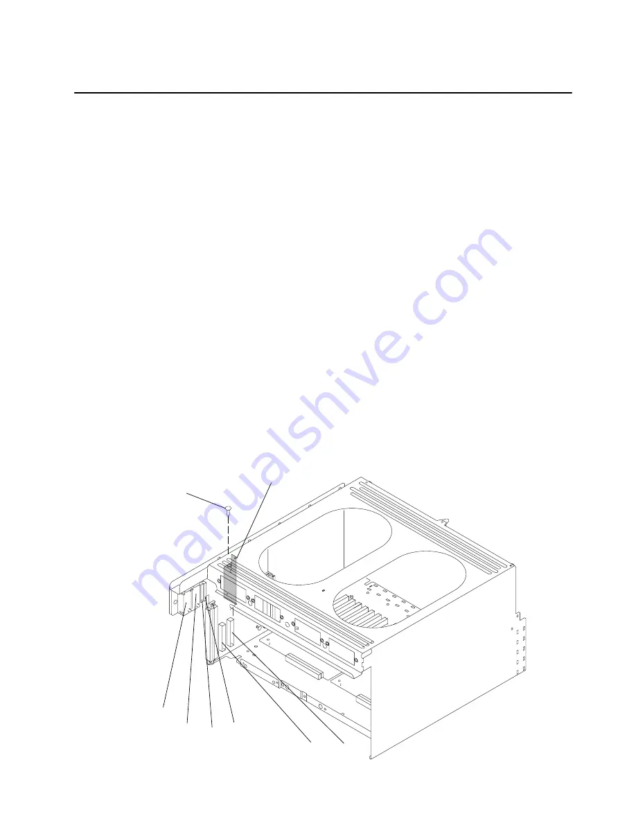
Removal
1. Perform the “I/O Module” removal procedure on page 4-67.
2. Disconnect connectors P10, P11, P12, P12A, P13, and P14.
3. Remove the mounting screw holding the air deflector, and then remove the air deflector.
P12
P13
P14
P10
P11
Mounting
Screw
Air Deflector
(Shaded)
P12A (Models
R40 and R50)
Summary of Contents for 7015-R50
Page 1: ...7015 Models R30 R40 and R50 CPU Enclosure Installation and Service Guide...
Page 10: ...x Service Guide...
Page 14: ...xiv Service Guide...
Page 34: ...1 20 Service Guide...
Page 214: ...6 10 Service Guide Detail 5 CPU Module 2 of 3 26 27 29 30 31 32 33 34 28 35...
Page 216: ...6 12 Service Guide Detail 6 CPU Module 3 of 3 36 37...
Page 252: ...B 8 Installation and Service Guide...
Page 288: ...Service Guide D 30...
Page 299: ......


