


3746-900 and service processor installation
Connection to Main Power
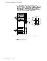
Install the 3746-900 close to the 3745 or 3746 frame to avoid any problem later in
routing the cables between the machines.
Power Description and Load Requirements
Note: The following procedures apply to both basic and optional power attach-
ments and must be performed twice if an AC optional power attachment is installed
on the machine. If you received a controller expansion, the customer must
provide a separate 220V ac power receptacle to connect the units installed in the
controller expansion.
Power Attachment Configuration
Basic Attachment: Single Power Supply: The basic attachment is ac connected
to input AC-1 (see Figure B-14 on page B-10).
Optional Attachment: Dual Power Supply Feature: The optional ac attachment
is connected to the input AC-2
There is no internal relation (or connection) between AC-1 and AC-2.
Therefore, AC-2 voltage and frequency can be different from those of AC-1 (see
Figure B-12 on page B-9 or Figure B-13 on page B-9).
Power Requirements
1. Basic AC-1 power input:
The standard voltage input to the 3746-900 is single-phase, 200 to 240 volts 60
Hz, or 200 to 240 volts 50 Hz. The maximum power requirement is 2.5 kVA.
2. Optional AC-2 power input:
Voltage and frequency limits are the same as for AC-1.
Note for World Trade: This product allows connection to an impedance grounded
(impedance "terre" or IT) power system.
(An IT power system is a power distribution having no direct connection to earth,
the exposed conductive parts of the electrical installation being grounded.)
Controller Expansion Power Requirements
The power input to the ac outlet distribution box must be between 200 to 240V with
a total of 15 Amp. Maximum output per outlet is 6 Amp. A fuse of 7 Amp protect
this equipment.
2-24
3746-900: Installation Guide
Summary of Contents for 3746-900
Page 1: ...3746 Nways Multiprotocol Controller Model 900 IBM Installation Guide SY33 2114 03...
Page 2: ......
Page 3: ...3746 Nways Multiprotocol Controller Model 900 IBM Installation Guide SY33 2114 03...
Page 14: ...xii 3746 900 Installation Guide...
Page 17: ...Notices xv...
Page 20: ...7 Power ON indicator 8 Emergency power OFF xviii 3746 900 Installation Guide...
Page 24: ...xxii 3746 900 Installation Guide...
Page 26: ...xxiv 3746 900 Installation Guide...
Page 40: ...3746 900 preparing for installation 1 14 3746 900 Installation Guide...
Page 102: ...3746 900 Test Procedure 3 14 3746 900 Installation Guide...
Page 146: ...Cabling the 3746 900 to the 3745 X1A 4 44 3746 900 Installation Guide...
Page 168: ...3745 Test Procedures 7 6 3746 900 Installation Guide...
Page 198: ...3746 900 Ground Bracket Installation 9 6 3746 900 Installation Guide...
Page 204: ...3746 900 Attached to a 3745 17A Ground Bracket Installation 10 6 3746 900 Installation Guide...
Page 210: ...Machine Ready for Customer 11 6 3746 900 Installation Guide...
Page 218: ...Removal the 3746 900 Attached to a 3745 17A 13 4 3746 900 Installation Guide...
Page 220: ...A 2 3746 900 Installation Guide...
Page 250: ...E 14 3746 900 Installation Guide...
Page 268: ...X 18 3746 900 Installation Guide...
Page 272: ......
Page 275: ......
Page 276: ...IBM Part Number 29H4858 Printed in Denmark by IBM Danmark A S 29H4858 SY33 2114 3...


