background image

4. Operation of SEP

 Related Controllers


261 

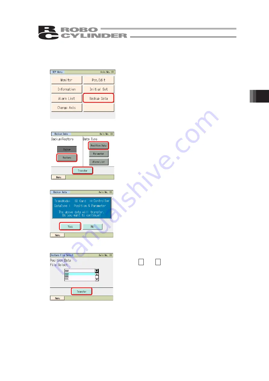
4.15.2  Restore to Controller 


Data in the Secure Digital card is transferred to the controller.


Touch [Backup Data] on the SEP Menu screen.


A window for data transfer appears.


Touch [Restore]. 


Select the data type to transfer to the controller, such as 

[Position Data], and touch it.


Touch [Transfer].


Touch [Yes].


If [No] is touched, the screen goes back to the data backup 

screen.


Touch 

 and 

  to select a file to transfer to the 

controller from the list of the backed up file names.


Touch [Transfer].


Summary of Contents for TB-02

Page 1: ...nual Fifth Edition This instruction manual describes the contents for position CON SEP MEC system controllers and ELECYLINDER For how to use the position SEL system controllers refer to the following instruction manual Touch Panel Teaching TB 02 Program Controller Instruction Manual ME0356 For details of applicable controllers refer in the section for the supported models ...

Page 2: ......

Page 3: ...g the Instruction Manual keep it in a convenient place so that whoever is handling this product can reference it quickly when necessary Important This Instruction Manual is original The product cannot be operated in any way unless expressly specified in this Instruction Manual IAI shall assume no responsibility for the outcome of any operation not specified herein Information contained in this Ins...

Page 4: ... 00 DCON V1 00 MSEP V1 00 PCON V1 00 AMEC V1 00 SCON Note 3 V1 00 PMEC V1 00 MCON Note 2 V1 00 RACON V1 00 MSCON V1 00 RPCON V1 00 RCP6S V1 00 RCON V2 10 RCM P6 C V1 50 ELECYLINDER Refer to Next Page Note1 Only ERC2 models with 4904 or higher stamped on the Serial No sticker can be connected Information on sticker I O type Not supported Supported NP NP U5 M NP T1 4904 4905 6302 PN PN U3 M PN T1 49...

Page 5: ...re not Update the version to V2 00 or later when use Note2 EC RR H is available for connection in versions from V1 60 to V2 01 however some models are not Update the version to V2 10 or later when use Applicable Models for Gateway Parameter Setting Tool Shown below are the models supporting the gateway parameter setting tool Controller model Supported from version MSEP C V1 00 MCON C CG Note 4 V1 ...

Page 6: ......

Page 7: ... the Specifications 14 2 Connection 24 3 Operation of CON Related Controllers 27 4 Operation of SEP Related Controllers 188 5 Operation of MEC Related Controllers 263 6 Operation of ELECYLINDER 323 7 Gateway Parameter Setting Tool 378 8 Error Display 393 9 Appendix 399 10 Warranty 404 ...

Page 8: ...cting with the Controller 24 2 2 Position controller ELECYLINDER cable 25 2 3 Safety Category compliance 26 3 Operation of CON Related Controllers 27 3 1 Displayed Language Change 27 3 2 Operating Menu 29 3 3 Initial Screen 31 3 4 Changing Operating Axis 32 3 5 Menu Selection 33 3 6 Position Edit Guide 35 3 7 I O Control Guide 37 3 8 Easy Program Setting 40 3 9 Monitor 42 3 9 1 Monitor Screen 43 3...

Page 9: ...ocity 118 3 20 2 Operation to Automatically Set Velocity and Acceleration Speed from Moving Distance 120 3 21 Maintenance Parts List 123 3 21 1 Check Cable Model Number Controller Parts 123 3 21 2 Schematic Display and Parts List Display 125 3 22 Easy programming 127 3 23 Pulse Train Mode Setting 131 3 23 1 Configuration setting 132 3 23 2 Electric gear setting 133 3 23 3 Feedback pulse configurat...

Page 10: ...s 188 4 1 Transition of Operating States 188 4 2 Operating Menu 189 4 3 Initial Screen 191 4 4 Initial Setting 192 4 5 Changing Operating Axis 193 4 6 Menu Selection 194 4 7 Monitor 195 4 8 Information 197 4 9 Alarm List 199 4 10 Position Setting Setting of Position related Data Jog Inching Operation 201 4 11 I O Setting Setting of Operation Parameters Etc 225 4 12 Parameters Parameter Editing Axi...

Page 11: ...ion 348 6 9 3 Direct Movement Operation 349 6 9 4 I O Test 349 6 10 TP Operation Mode 350 6 11 Alarm List 351 6 12 Controller Reset 352 6 13 Other Setting 353 6 13 1 Parameter Initialization 353 6 13 2 Axis Number Change 354 6 14 Information Display 355 6 14 1 Axis Name Edit 357 6 15 Environment Setting 359 6 16 Data Backup 368 6 16 1 Data Backup of the Controller 369 6 16 2 Restore to Controller ...

Page 12: ...w to Update when CON System Controller Connected 400 9 2 3 How to Update when SEP System Controller Connected 402 9 2 4 How to Update when MEC System Controller Connected 403 10 Warranty 404 10 1 Warranty Period 404 10 2 Scope of Warranty 404 10 3 Honoring the Warranty 404 10 4 Limited Liability 404 10 5 Conditions of Conformance with Applicable Standards Regulations Etc and Applications 405 10 6 ...

Page 13: ...ant safety parts of machinery Safety device etc Do not use the product outside the specifications Failure to do so may considerably shorten the life of the product Do not use it in any of the following environments 1 Location where there is any inflammable gas inflammable object or explosive 2 Place with potential exposure to radiation 3 Location with the ambient temperature or relative humidity e...

Page 14: ...the safety factor of the hook in such factors as shear strength Do not get on the load that is hung on a crane Do not leave a load hung up with a crane Do not stand under the load that is hung up with a crane 3 Storage and Preservation The storage and preservation environment conforms to the installation environment However especially give consideration to the prevention of condensation Store the ...

Page 15: ...is no disconnection or looseness Failure to do so may cause a fire electric shock or malfunction of the product Never cut and or reconnect the cables supplied with the product for the purpose of extending or shortening the cable length Failure to do so may cause the product to malfunction or cause fire 3 Grounding The grounding operation should be performed to prevent an electric shock or electros...

Page 16: ... to secure safety Do not insert a finger or object in the openings in the product Failure to do so may cause an injury electric shock damage to the product or fire When releasing the brake on a vertically oriented actuator exercise precaution not to pinch your hand or damage the work parts with the actuator dropped by gravity 5 Teaching When the work is carried out with 2 or more persons make it c...

Page 17: ...minal block or any of the various setting switches in the power ON mode Failure to do so may result in an electric shock or malfunction 7 Automatic Operation Check before starting the automatic operation or rebooting after operation stop that there is nobody in the safety protection fence Before starting automatic operation make sure that all peripheral equipment is in an automatic operation ready...

Page 18: ...sult in a damage to the product When releasing the brake on a vertically oriented actuator exercise precaution not to pinch your hand or damage the work parts with the actuator dropped by gravity The slider or rod may get misaligned OFF the stop position if the servo is turned OFF Be careful not to get injured or damaged due to an unnecessary operation Pay attention not to lose the cover or untigh...

Page 19: ...he product is not handled correctly will result in death or serious injury Danger Warning This indicates a potentially hazardous situation which if the product is not handled correctly could result in death or serious injury Warning Caution This indicates a potentially hazardous situation which if the product is not handled correctly may result in minor injury or property damage Caution Notice Thi...

Page 20: ...operated by stronger force than that The life of the touch panel is around one million times under the condition of depression at the same point Based on the usage environment of 25 degrees C Turn off the power to the controller before putting it in or out Putting it in and out while the power is on may cause malfunction When putting it in check the connector matching position and insert it carefu...

Page 21: ...ernational Standards Compliances This product comply with the following international standards Refer to Overseas Standard Compliance Manual ME0287 for more detailed information RoHS Directive CE Marking UL ...

Page 22: ... 1 Standard cable is affixed on body Accessories 2 Position controller ELECYLINDER cable CB TB1 C002 1 When model C or SC is selected 3 Program controller cable CB TB1 X002 1 When model S or SC is selected 4 Replacement Cable CB SEL SJS002 1 When model S or SC is selected 5 Touch pen TCH TB02 1 Provided with the teaching pendant 4 5 102mm 6 Safety guide 1 The picture shows an image 7 First step gu...

Page 23: ...B controller ME0354 9 Instruction manual for PCON CA CFA controller ME0289 10 Instruction manual for PCON CB CGB CFB CGFB controller ME0342 11 Instruction manual for PCON CYB PLB POB controller ME0353 12 Instruction manual for SCON CA CAL CGAL controller ME0243 13 Instruction manual for SCON CB CGB LC LCG controller ME0340 14 Instruction manual for SCON CB F CGB F LC F LCG F controller ME0345 15 I...

Page 24: ...s switch type left stop switch portion in gray TB 02D S SWR Dead man s switch type left stop switch portion in red Note Language option can be indicated in the last digit of the unit model code Displayed in Japanese when no indication 1 Screens are displayed in English ENG 2 Screens are displayed in Chinese CHI Model code for main unit itself Model code for enclosed cable Remark CON SEL Common Sin...

Page 25: ...nd MSEL Connection used together with CB TB1 X002 CB TB1 XJ005 For XSEL J JX connection CB TB1 GC002 For positioner controller TP adapter connection to comply with Safety Categories Option model code Remark Strap STR 1 Grip Belt GRP 1 Do not assemble during preparation Spiral Cord SIC 1 Connect the stylus pen on the main unit in order to avoid loosing or dropping it Maintenance part code Remark To...

Page 26: ...h pen Accessory 4 5 102mm Language selection Japanese English Chinese Touch sound ON OFF Volume Settable in 3 steps S M and L Data save Applicable to have data saved to and read from external Secure Digital memory card FAT32 Format Position data parameter alarm list Display adjustment Brightness adjustable for contrast and backlight Time setting Clock setting available with real time clock Backup ...

Page 27: ...meters or less above the sea level Environment Environment with no corrosive or flammable gas Avoid use in places with dust or in places where oil mist or cutting fluid splashes Vibration resistance Frequency 10 to 57Hz Swing width 0 035mm Continued 0 075mm Continual Frequency 57 to 150Hz Acceleration 4 9m s2 Continued 9 8m s2 Continued XYZ Each direction Sweep time 10 min Number of sweep 10 times...

Page 28: ...ove it from the controller when it is not in use Set the turn off time in the environment setting so it automatically turns OFF 2 This touch panel is of analog resistance membrane type so do not touch two or more locations on the screen at the same time If two or more locations are touched at the same time the centers of all touched locations may respond and trigger multiple operations 3 When oper...

Page 29: ...Man s Switch Type 6 Wall mounting hook unit 6 Wall mounting hook unit 5 Touch pen 4 Secure Digital Memory Card Slot Cover Inside Secure Digital memory card inlet 4 Secure Digital Memory Card Slot Cover Inside Secure Digital memory card inlet 5 Touch pen 7 Dead Man s Switch unit ...

Page 30: ...Dead man s Switch unit It is not equipped on the standard type The dead man s switch has three conditions corresponding to three levels The meaning of ON OFF in each condition is explained below Level 1 Switch OFF The hand is off the switch or the switch is pressed with a very small force Level 2 Switch ON The switch is pressed with an appropriate force Level 3 Switch OFF The switch is pressed wit...

Page 31: ...1 4 1 How to Take off Secure Digital Memory Card Slot Cover Slide it towards the back while pushing it against the unit 1 4 2 How to Insert Secure Digital Memory Card Face the electrode side of a Secure Digital memory card to the front and push it in until it makes a click sound Slide ...

Page 32: ...Specifications 20 1 4 3 How to Take out Secure Digital Memory Card Press the Secure Digital memory card lightly and release and the card pops out a little Pull it out straight Press the card lightly Pull it out straight ...

Page 33: ...1 Confirming the Specifications 21 1 5 External Dimensions Dead manʼs switch type Standard type with no dead manʼs switch ...

Page 34: ...minal life of the button battery CR2032 that the manufacturer states is approximately five years Ambient temperature at 25 C The replacement of the battery cannot be held at customer s site Please contact IAI when you require a replacement 1 8 Optional Items IAI Products Grip Belt GRP 1 for support to hold on left hand Spiral Cord SIC 1 for stylus pen connection Touch Pen enclosed to main unit for...

Page 35: ...rt from the grip part 2 Attach the belt at the slit on the left bottom of the main unit 3 Put the belt part through the grip part 4 Attach the belt at the slit on the left top of the main unit and attach the belt to the grip part with the fabric hook and loop fastener Belt part Grip part ...

Page 36: ...ller Turn the controller power OFF before connecting or disconnecting the touch panel teaching TB 02 Caution Connecting or disconnecting the unit while the controller power is ON could result in faults Confirm the connector engagement section and connect disconnect while taking care not to apply excessive force If the connector does not fit in smoothly do not push it in with force Failure to obser...

Page 37: ... cable Model CB TB1 C002 Name TB 02 Position controller ELECYLINDER connection cable Controller side connector type MD connector JST Mfg Co Ltd TB 02 unit side connector type RP13A 12PH 20SC 71 HIROSE Minimum Cable Bending Radius 48mm Cable length φ6 0 ...

Page 38: ... standard cable Note When not connecting the TB 02 always insert a dummy plug DP 4S into the position controller s TP adapter The applicable category level differs depending on the controllers Controller Position controller TP adapter RCB LB TGS Controller adaptor Connection cable Type CB CON LB Safety circuit Standard Cable 5m Dummy plug DP 4S Safety Category compatible cable CB TB1 GC002 Minimum...

Page 39: ...e instruction manual written in each language Display change from English to Japanese 1 Touch Menu2 in Menu1 2 Touch Environment Setting in Menu2 3 Touch Japanese 4 Touch 上記設定を書き込み Note Skipping to another window without touching 上記設定を書き込み will allow setting to go back to that before changed Display change from Japanese to English 1 Touch メニュー2 in メニュー1 2 Touch 環境設定 in メニュー2 3 Touch 英語 4 Touch Wri...

Page 40: ... 写入上述设定 Note Skipping to another window without touching 写入上述设定 will allow setting to go back to that before changed Display change from Chinese to English 1 Touch 菜単 2 in 菜単 1 2 Touch 环境设定 in 菜単 2 3 Touch 英语 4 Touch Write the above setting Note Skipping to another window without touching Write the above setting will allow setting to go back to that before changed ...

Page 41: ...date Guide position data edit Input position data and explain how to make a trial run in two way communication style Guide I O control method Explain how to make I O control in two way communication style Guide operationdata setting and how to have trial run Explain how to set the operation data and how to make a trial run in two way communication style Servo monitor Servo Monitor Waveform Display...

Page 42: ...peration stop setting continuous operation and repeated operation Offboard Tuning Setting of each types of Gain Cycle Time Calculation Setting of pulse train control operation parameter Setting of pulse train control operation parameter Move to menu 1 Menu 1 window display TP Operation Mode TP Operation Mode Window Menu 1 Menu 1 Window Global Window System Password Change Window Position Editing P...

Page 43: ...with TB 02 Refer to 3 4 Changing Operating Axis 2 On TB 02D pendants this screen is displayed when the enable function parameter of the controller is set to Disable The Menu 1 screen appears Select either Yes Activate Enable Feature or No Inactivate Enable Feature 1 On TB 02 pendants this screen is displayed when the enable function parameter of the controller is set to Enable Select either Yes In...

Page 44: ...the axis to be operated in the touch panel teaching pendant and touch it Connection with the selected controller axis starts The following screen is shown when the enable feature parameter of the controller is valid in TB 02 Select either Yes Inactivate Enable Feature or No Activate Enable Feature The following screen is shown when the enable feature parameter of the controller is invalid in TB 02...

Page 45: ...enu 2 Select one of them and touch it The screen goes to the touched menu Menu 1 list Position edit guide Explains how to input position data and how to make a trial run in two way communication style using the actual position data edit screen Refer to 3 6 Position Edit Guide I O control guide Explains with actual operation how to perform positioning operation by I O control when PIO Pattern is se...

Page 46: ... 2 list Change operation axis Select an axis to operate when multiple units of controllers are connected to the communication line Refer to 3 4 Operation Axis Change TP op mode Switch over between forbidden and permitted for PIO operation and between invalid and valid for the safety velocity Refer to 3 13 TP Operation Mode Env set Conduct settings for display language touch sound turn off time dat...

Page 47: ...the order of Introduction Item select Position input Test run End Touch Position edit guide icon After that follow the instruction on the screen to operate Touch button and the screen goes back to the previous window Some processes may be skipped depending on the actuator condition For the terms bracketed with touch Glossary button at the bottom right of the screen and the explanation can be confi...

Page 48: ...3 Operation of CON Related Controllers 36 Positioning operation Push operation Touch the home button to return to Menu 1 screen Test run End Position input ...

Page 49: ...ol guide icon This window appears when PIO Pattern Select is set to a number except for 0 Confirm that there would be no problem if a change is made to the parameter set PIO Pattern Select to 0 and then select this guide menu Follow the following descriptions to perform operation Touch button to return to the previous screen There may be some procedures to skip depending on the condition of the ac...

Page 50: ...3 Operation of CON Related Controllers 38 Servo ON Release of pause Homing Expl for pos ...

Page 51: ...3 Operation of CON Related Controllers 39 Touch the home button to return to Menu 1 screen Positioning End ...

Page 52: ...tion in order of Sample program select Stop p select Position d create Test run End Touch Easy setting icon Follow the following descriptions to perform operation Touch button to return to the previous screen There may be some procedures to skip depending on the condition of the actuator Also for those terms marked with explanation can be checked by touching Glossary on the right bottom of the scr...

Page 53: ...3 Operation of CON Related Controllers 41 Touch the home button to return to Menu 1 screen Pos d create Test run End ...

Page 54: ...n appears Touch Yes to change to Monitor Mode 1 or 2 If not touch No Note The safety speed does not change If the current mode is Teaching Mode 1 it changes to Monitor Mode 1 If the current mode is Teaching Mode 2 it changes to Monitor Mode 2 Touch OK The main monitor screen appears The items and buttons to be shown will differ depending on the controller models The signal names to be shown will a...

Page 55: ...uch Production info and the manufacturing information screen will be displayed Refer to 3 9 17 Touch Maint and the maintenance information screen will be displayed Refer to 3 9 2 Touch Time and the controller clock setting screen will be displayed Refer to 3 9 3 Touch Disp change cur and the value of current will be displayed Touch Cur ratio disp change and the current ratio will be displayed For ...

Page 56: ...s unlit Homing The home return status is shown Lit if home return has completed Cur pos The current position is shown Cur vel The current speed is shown Cur Shows the command current Cur ratio The command value of electrical current is shown as a percentage of the rated current Alarm code The applicable alarm code is shown Controller S N Shows the manufacturing number of the controller The items a...

Page 57: ...models The signal names to be shown will also differ depending on the controller models and operation patterns 3 9 1 3 Data Monitor Screen Touch Monitor main and the monitor main screen will be displayed Refer to 3 9 1 1 Touch I O monitor and the I O monitor screen will be displayed Refer to 3 9 1 2 Touch Disp change cur and the value of current will be displayed Touch Cur ratio disp change and th...

Page 58: ...return status is shown Lit if home return has completed Control Voltage The voltage of the control power supply is shown Motor V The voltage of the motor power supply is shown PCB temp The PCB temperature is shown The items and buttons to be shown will differ depending on the controller models The signal names to be shown will also differ depending on the controller models and operation patterns 3...

Page 59: ...n Control Signal 1 and Control Signal 2 of input and Status Signal 1 and Status Signal 2 of output should be displayed in the binary numbers or hexadecimal numbers Touch Binary button and the values are displayed in binary numbers Touch Hexadecimal button and the values are displayed in hexadecimal numbers Displays Network setting Refer to 3 9 1 5 1 Data monitor Positioner Type Refer to 3 9 1 5 2 ...

Page 60: ... Output Format should be displayed The setting will be reflected to the input and output values in the data monitor Fieldbus input output format setting Parameter No 90 Setting Name 0 No swapping should be conducted Data is to be sent as it is to PLC 1 Upper bytes and lower bytes in each resistor should be swapped 2 Upper words and lower words in two word resistors should be swapped 3 Upper bytes ...

Page 61: ... Fieldbus Operation Mode 3 Full Direct Shown in Input and Output Display List for Each Positioner Type Fieldbus Operation Mode is the screen displayed in each setting of Fieldbus Operation Mode Positioner Type Input and Output Display List for Each Fieldbus Operation Mode Fieldbus Operation Mode Input Value Output Value 0 Remote I O Network data monitor should not be displayed 1 Simple Direct 2 Ha...

Page 62: ...3 Operation of CON Related Controllers 50 Fieldbus Operation Mode Input Value Output Value 4 Remote I O2 5 Simple Direct 2 6 Half Direct 2 7 Remote I O 3 8 Half Direct 3 ...

Page 63: ... on positive Command speed Command speed Pressing current limit Zone boundary on negative Pressing current limit Pressing current limit Control signal Accelerate Control signal Control signal Decelerate Load Current Threshold Control signal 1 Control signal 2 Output Transition to network monitor information window cannot be conducted Current position Current position Current position Current posit...

Page 64: ...Unit 0 01mm or 0 001mm Range available to indicate 999999 to 999999 7 Accelerate It shows the acceleration at direct position movement command Unit 0 01G 8 Decelerate It shows the deceleration at direct position movement command Unit 0 01G 9 Pressing current limit It shows the current limit value in the pressing operation 10 Load current threshold It shows the threshold of the pressing motion 11 S...

Page 65: ...It shows the total number of movement 7 Total travelled distance It shows the total travelled distance 8 Completed position No Is shows the completed position number 9 Status signal It shows the status signal Output should be displayed in the binary numbers or hexadecimal numbers Refer to Positioner Type Control Signals and Status Signals List for show to set it up 10 Status signal 1 It shows the ...

Page 66: ...E GSL0 GSL0 GSL0 11 PMOD GSL1 PMOD GSL1 GSL1 12 PUSH NTC0 PUSH PUSH 13 DIR NTC1 DIR DIR 14 RMOD PMOD PMOD RMOD PMOD PMOD 15 BKRL BKRL BKRL BKRL BKRL BKRL Bits 0 1 2 3 4 5 6 7 8 Controlsignal1 Controlsignal 2 Output 00 PEND PEND BALM PEND PEND PEND PEND 01 HEND HEND CEND HEND HEND HEND HEND 02 MOVE MOVE MOVE MOVE MOVE MOVE 03 ALM ALM ALM ALM ALM ALM 04 SV SV SV SV SV SV 05 PSFL PSFL PSFL PSFL PSFL ...

Page 67: ... Press Type Input List Item Explanations 1 Position It shows the target position at direct position movement command Unit 0 01mm or 0 001mm 2 Pos band It shows the positioning band at direct position movement command Unit 0 01mm or 0 001mm 3 Vel It shows the velocity at direct position movement command Unit 0 01mm s 4 Acc It shows the acceleration at direct position movement command Unit 0 01G 5 D...

Page 68: ...ion command 04 RMOD Operation mode switchover 05 BKRL Brake compulsory release 06 PSTR Program startup 07 PHOM Program home position movement 08 ENMV Axis operation permission 09 FPST Program compulsory stop 10 SSTP Searching stop 11 JISL JOG Inching switchover 12 JVEL JOG velocity Inching distance switchover 13 JOG JOG Command 14 JOG JOG Command 15 DSTR Direct Positioning Startup Command ...

Page 69: ...de which is currently being occurred It shows 0000 when an program alarm is not occurred 6 Alarm Code It shows the alarm code which is currently being occurred It shows 0000 when an alarm is not occurred 7 Overload level It shows the overload level 8 Executed Program Number It shows the program number being executed by the program startup command It should be 1 before the pressing program is execu...

Page 70: ...e Judgment Failure 12 LJOK Load Judgment Passed 13 LJNG Load Judgment Failure 14 JDOK Total Judgment Passed 15 JDNG Total Judgment Failure Servo Press Type Control Signal 2 Details Bits Symbol Name 00 SV Servo on Status 01 HEND Home Return Complete 02 CEMD Loadcell Calibration Complete 03 RMDS Operation Mode Status 04 PEND Positioning Completion 05 Reserved 06 ZONE1 ZONE 1 07 ZONE2 ZONE 2 08 PCMP ...

Page 71: ... cumulative total number of actuator movements is shown Total travel count threshold A notice should be made with an alarm when the total number of movement times has exceeded this setting value Total travel distance The cumulative total distance travelled by the actuator is shown Total travel distance threshold A notice should be made with an alarm when the total distance of drive has exceeded th...

Page 72: ...rm to be Output Alarm code Name Description 04E Exceeded Movement Count Threshold It should be issued when the movement count has exceeded the movement count threshold Parameter No 147 04F Exceeded Operated Distance Threshold It should be issued when the operated distance has exceeded the operated distance threshold Parameter No 148 Example of use of Total travel distance For example when using th...

Page 73: ...s equipped with a battery less absolute encoder The controller has the mechanism that if the encoder ID is different after checking the ID then the absolute encoder error is output When replacing with the actuator which is absolutely reset the last ID pairing ID of the actuator must be cleared Touch Yes The Total travel count and Total travel distance are reset to 0 The Actuator replacement time s...

Page 74: ...n only motor unit is to be replaced Follow the process in 3 9 2 1 Operating Method When Replacing the Actuator when replacing an actuator Touch Pairing ID clear to display the password entry screen Enter 5119 and then touch ENT The controller has the mechanism that if the encoder ID is different after checking the ID then the absolute encoder error is output When replacing with the actuator which ...

Page 75: ... at the time of the fan replaced The total fan operation time and FAN replacem button should be shown only when the controller is equipped with a fan Touch FAN replacem to display the password entry screen Enter 5119 and then touch ENT The FAN total runninng time clear confirmation screen appears Touch Yes The FAN total running time is reset to 0 ...

Page 76: ...h the controller and actuators are applicable for the information management system and Parameter No 192 Actuator Identification System Use Flag is set to 1 Valid Touch Lubrication to display the password entry screen Enter 5119 and then touch ENT Lubrication information clear confirmation window should be displayed Touch Yes Confirmation window for controller reboot should appear Touch Yes If tou...

Page 77: ...et How to Set Time Touching Time displays the time setting screen Controller s time is displayed Touch Time edit Touch the value of year month day hours minutes or seconds you want to change The numeric key pad appears Enter a desired value and then press ENT Touch Set A screen telling the clock setting is complete appears and then the controller clock will be displayed ...

Page 78: ... Pos Edit Password A position data table appears Touch No sel to set the position number you want to set and a table showing the position number you have just set appears To set data other than the target position speed acceleration and deceleration shown in the table touch other position number such as 000 Data of the selected position number appears Position Data Individual Edit Screen Touching ...

Page 79: ...umber is shown Warning Be sure to specify absolute coordinates on PCON C CF CA CFA CB CFB CYB ACON C CA CB CYB DCON CA CB CYB SCON C CA CAL CB ROBONET ERC3 PIO Converter RCP6S MCON MSCON Remote I O mode controllers of solenoid valve mode 2 or PCON CY CYB ACON CY CYB and DCON CYB controllers of solenoid valve mode 1 same for Safety Category Complied Type If incremental coordinates are specified on ...

Page 80: ...A CFA CB CFB CYB ACON CA CB CYB DCON CA CB CYB ERC3 RCP6S MCON and MSCON an alarm will be displayed if the set value exceeds the rated acceleration deceleration Caution Acceleration deceleration setting 1 Set accelerations decelerations not exceeding the rated acceleration deceleration specified in the catalog or in the instruction manual of the actuator If any acceleration deceleration is set tha...

Page 81: ...s of solenoid valve mode 1 set the band after which the completion signal turns ON same for Safety Category Complied Type PCON C CF CA CFA CB CFB ACON C CA CB DCON CA CB SCON C CA CAL CB ROBONET ERC3 PIO Converter RCP6S MCON and MSCON Remote I O mode in solenoid valve mode 2 PCON CY CYB ACON CY CYB and DCON CYB in solenoid valve mode 1 same for Safety Category Complied Type Push motion operation D...

Page 82: ...rollers a position data error occurs 8 Zone mm Define for the standard type the zone in which the zone output signal turns ON These parameters can be set differently for each target position Setting example No Position mm Zone mm Zone mm Remarks 0 5 00 100 00 0 00 Backward end 1 380 00 400 00 300 00 Forward end 2 200 00 250 00 150 00 Intermediate position Movement command to backward end Movement ...

Page 83: ...t to 100 If 0 is set the S motion control is disabled Note that the setting made here is not reflected in jogging or inching feed performed from a PC or teaching pendant Note This setting is not available on ERC2 and PCON excluding PCON CA CFA CB CFB controllers On these controllers parameter No 56 is reserved Primary delay filter The acceleration deceleration curve becomes more gradual than linea...

Page 84: ...nsumption is reduced When the PLC issues the next movement command the servo is turned ON and then the actuator starts moving Note For RACON and RPCON this mode cannot be set Full servo control mode selectable for the PCON for the pulse motor controller The holding current can be decreased by servo controlling the pulse motor Although the rate of decrease in holding current varies depending on the...

Page 85: ...e row comment Touch on the line set as a one row comment and a confirmation window asking Do you change the one row comment to the position data should appear Touch Yes to set it back to position data Touch the comment box in a comment or a one row comment and the full keyboard should open and input in half size alphabetical and numerical symbols will get available If you use the PC software full ...

Page 86: ...for movement current limitation at position movement can be established Push speed Setting for pressing velocity limitation at position movement can be established 4 Linked Number A position number to move to in a row after a movement has finished can be set Make it blank and linked operation will get invalid If you want it blank touch CLR and ENT 5 Wait Time When the setting is established for th...

Page 87: ...4 Inching Use Forward or Backward to inch the actuator to the target position and then acquire the achieved position current position into the position data table and specify that position Touching Forward or Backward once moves the actuator by the specified feed pitch 0 01 0 10 0 50 1 00 or 5 00 mm Touching and holding the key for 2 seconds will start jogging movement at 1 mm sec Thereafter the s...

Page 88: ...sition data Important Do not touch Pr pg key or Nx pg key too fast to switch the windows 0 is occasionally shown to the data values that are already registered The data is not lost even though 0 is displayed Touch Pr pg key and Nx pg key to switch the window and come back and you will find the data showing the right values Data Input in Position Data Individual Edit Screen In Position Data Individ...

Page 89: ...ange The jog speed changes in the order of 1 10 30 50 and 100 mm s every time Jog vel change is touched BACK FW While touching the axis moves in JOG BACK performs JOG operation in negative direction and FW in positive direction While Inching Selected Inc dis change Inching distance changes in order of 0 01 0 10 0 50 1 00 and 5 00mm s for every touch on Inc dis change BACK FW A touch performs inchi...

Page 90: ...ou would like to read by JOG Inching operation Touch the target position of the position number that you would like to read Touch Pos set button The confirmation window appears You can touch or to change the position number Touching Yes acquires the current position Return to the position edit window ...

Page 91: ...into the position data table and specify that position The axis moves by the specified pitch 0 01 0 10 0 50 1 00 or 5 00 mm every time FW or BACK is touched Touch and hold it for two seconds and JOG operation will be performed in 1mm sec The speed increases in every 1 second afterwards Severer movement than JOG operation is available Take note of the following points when performing a data change ...

Page 92: ...assword entry screen appears Input the parameter edit password Touch ENT A parameter table is displayed The types of parameters vary from one controller to another Refer to the instruction manual for each controller The parameter edit password at delivery is set to 0000 For how to change the parameter edit password refer to 3 18 Environmental Setting Parameter Edit Password Change ...

Page 93: ...eys are displayed touch ESC Touching the Home button opens a confirmation screen with a message asking if you want to restart the controller Touch Yes Touch No to return to the parameter screen without restarting the controller or reflecting the parameter you have set To reflect the parameter you have set you must restart the controller Caution If the controller is not restarted the parameter that...

Page 94: ...operations move to a position or continuously to multiple positions registered in the position table or move to a position by specifying the position directly Touch Test run on the Menu 1 screen The movement menu screen appears Select and touch Jog inching or other item you want to operate ...

Page 95: ... table has been set If a continuous movement command is issued from position No 2 the actuator operates over a group of positions from the position at which the movement command is issued through successive positions where data is available until the position before the one where no data is registered such as position No 2 No 3 No 1 No 2 and so on On a touch panel teaching pendant continuous movem...

Page 96: ...he speed on the numeric keys to perform movement Refer to 3 12 3 Direct Movement Operation for details about how to operate 4 I O test Monitoring of the PIO input signals and compulsory output of the output signals can be conducted Refer to 3 12 4 I O test for details about how to operate ...

Page 97: ... an actuator equipped with a brake touch Brake rel and the brake gets compulsorily released and the circle turns on Touch Brake rel again and the brake works and the circle turns off BACK FW When JOG operation is selected while touching them the axis moves in the set speed When inching operation is selected every time touching them the axis moves for the set distance BACK performs JOG operation in...

Page 98: ...hile the servo is OFF turns on the axis servo and becomes lit Touching Servo OFF while the servo is ON turns off the axis servo and becomes unlit Homing Touching Homing while home return is not yet completed causes the axis to return home and becomes lit Touch and to select a desired position number Change vel When Safety Velocity is Valid Speed can be changed in order of 1mm s 10 mm s 30 mm s 50 ...

Page 99: ... servo and becomes lit Touching Servo OFF while the servo is ON turns off the axis servo and becomes unlit Homing Touching Homing while home return is not yet completed causes the axis to return home and becomes lit Move Touching Move moves the axis to the target position you have set Stop Touching Stop stops the axis Caution Operation with JOG Switch on Front Panel of RCON If TB 02 gets disconnec...

Page 100: ...r operation commands Safety velocity invalid You can move the actuator at the speed greater than the safety speed set in the position data table Monitor1 Safety velocity valid PIO movement permittion PIO movement permittion Only monitoring is permitted You cannot write position data parameters etc to the controller or issue actuator operation commands Operation commands jog home return etc cannot ...

Page 101: ...list of the previous screen Touching Clear clears all alarm details Note PowerUP No Error indicates that the controller power was turned on It does not indicate an error The time of occurrence of each alarm is indicated by an elapsed time from this PowerUP No Error Controller with the calendar function Touching Pr pg displays the list of the previous screen Touching Nx pg displays the list of the ...

Page 102: ... Controller reset on the Menu 2 screen Touch Yes Touch No to return to the Menu 2 screen without restarting the controller This window appears if the servo is on Touch Yes Touch No to return to the Menu 2 screen without restarting the controller The controller is restarted Returns to Menu 1 Screen ...

Page 103: ...d like to conduct such as Parameter initialization 3 16 1 Parameter Initialization The parameters are reset to their factory default settings initialized Caution Once the parameters are initialized to their factory default settings all parameters the user has set will return to the values set at the factory Exercise caution Touch Parameter initialization in Other setting screen to display Paramete...

Page 104: ...y settings will become effective once the controller is restarted or power is reconnected 3 16 2 Axis Number Change Touch Change axis No in Other setting window to display Axis No setting screen You can set a value between 0 and 15 Set a desired axis number and then touch ENT Touch Execute 3 16 3 Load Cell Calibration Loadcell calibration can be conducted on an actuator equipped with a loadcell SC...

Page 105: ... signal CSTR should be assigned to the input ports and necessary number of complete position number signals PM and the positioning complete signal PEND to the output ports Desired signals from the indicated signals refer to Signals Available for Assignment can be assigned to the other ports Touch I O Customizing in Other Setting window to show the I O customizing window It is set to the initial as...

Page 106: ...nment Available for Assignment 64 points IN PC1 PC2 PC4 PC8 PC16 PC32 CSTR Available for Assignment OUT PM1 PM2 PM4 PM8 PM16 PM32 PEND Available for Assignment Initial Assignment at Delivery 64 点 IN PC1 PC2 PC4 PC8 PC16 PC32 CSTR RES OUT PM1 PM2 PM4 PM8 PM16 PM32 PEND ALM Signals Available for Assignment Any signal in the list of signals below can be selected For the detail of each signal please r...

Page 107: ...the output of these signals the current command current rate ratio to the rated value should be output In order to output the command current rate it is necessary that all of the four signals CM1 CM2 CM4 and CM are assigned With this as a reason it is available only when the number of positioning points is either four points or eight points PCON CYB outputs the current load current in every 6 25 p...

Page 108: ...ersion information Software version information Touch Software version information in Information screen Software version information screen opens In this shows the series type of the controller and versions of the controller and this teaching pendant Touch Edit Axis Name and the name of axes can be edited Refer to 3 17 1 Axis Name Edit for how to edit an axis name Network information Touch Networ...

Page 109: ...ser Note Editing button show the full keyboard and it is available to edit the memo The user note is available for editing up to 124 characters in half size at the maximum Only half size alphabetical and numerical characters and half size symbols are available for input in TB 02 Refer to Input Operation on Full Keyboard in 3 10 2 for entering a text Maintenance information Touch Maintenance inform...

Page 110: ...le model in Information screen Connectable model screen opens Controllers connectable to this teaching pendant with the current version should be displayed Refer to 9 2 Teaching Update for how to update teaching Inquiry Touch Inquiry in Information window Inquiry window opens ...

Page 111: ... for setting in TB 02 are capitalized font English characters from A to Z and numbers from 0 to 9 Axis Name Edit Operation 1 Set to Axis Name for the axis name display in Menu 2 Env set window 2 Touch Edit Axis Name button in Menu 1 Information Software version information screen On the right of the TP version display is the input area Character select buttons are shown in the half bottom of the s...

Page 112: ...on the Menu 2 screen The environment setting screen appears Servo Press Type Controller For the servo press type controllers Change Prs Program Edit Password button should be shown instead of Change Position Edit Password button language setting Select a language to show from Japanese English EU Chinese Touch a language such as Japanese to show Touch Write the above setting Note Skipping to anothe...

Page 113: ... before making a change when moving to another screen Data input warning The warning can be output when a value less than the minimum speed and a value exceeding the rated acceleration deceleration speed are entered in the position data Note that the value is entered even if the warning occurs Always use within the specification of the actuator Touch Enable to give the warning Touch Disable not to...

Page 114: ... password change or Prs Program edit password change If the system password is not 0000 the password entry screen appears Input a system password Touch ENT Enter the new position edit password Prs Program edit password change to change to If the position edit password is not set enter 0000 Touch ENT Touch Change The new password after change will be displayed Make sure it shows the same as the pas...

Page 115: ...n appears Input a system password Touch ENT Enter the new parameter edit password to change to If the parameter edit password is not set enter 0000 Touch ENT Touch Change The new password after change will be displayed Make sure it shows the same as the password you have set Touch OK The default system password is 5119 For how to change the system password refer to Change System Password in the ne...

Page 116: ... the password entry screen appears Input the system password that is currently set Touch ENT Enter the new system password to change to If you do not set the system password enter 0000 Touch ENT Touch Change The new password after change will be displayed Make sure it shows the same as the password you have set Touch OK The default system password is 5119 ...

Page 117: ...play setting Display setting menu window is displayed Select Display setting menu Change the Contrast Brightness You can adjust contrast shading of liquid crystal and brightness of liquid crystal Touch Contrast Brightness Contrast adjustment Touch and under Contrast to adjust the contrast of the screen Brightness adjustment Touch and under Brightness to adjust the brightness of the screen ...

Page 118: ...ers 106 Touch panel position calibration A calibration for the position detection of the touch panel is performed Touch Touch panel position calibration Touch in the order of 1 2 3 and 4 The display returns to Display setting menu screen ...

Page 119: ...the order of Color Pattern White Only and Black Only Touch LCD check Color Pattern is displayed Touch any point on the screen White Only is displayed Touch any point on the screen Black Only is displayed Touch any point on the screen The display returns to Display setting menu screen ...

Page 120: ...2 or controller with the calendar function 1 Time setting for TB 02 Touch Time The time of teaching TB 02 is displayed Touch Time edit Touch the value of year month day hour minute or second that is required to be changed Numeric keys are displayed Input a value and touch ENT Touch Set ...

Page 121: ... for controller with the calendar function Touch Time Teaching time is displayed Touch Time edit You don t need to change the time in the case of setting the time of the teaching to the controller Touch the value of year month day hour minute or second that is required to be changed Numeric keys are displayed Input a value and touch ENT ...

Page 122: ...3 Operation of CON Related Controllers 110 Touch Set as controller clock The clock setting complete screen is shown and the clock in the controller gets changed ...

Page 123: ...the guide icons Note 1 Main menu screen without guide Displays no guide icon Note 1 Touch OK Note1 Position edit guide Icon I O control guide Icon and Easy setting Icon Menu 1 screen with guide icons Note 1 hidden 2 Initial Screen Select at Startup Select a screen from those below for the screen shown first after the power is turned on Monitor screen Position edit screen Parameter edit screen Test...

Page 124: ...sions in the RC PC Software Instruction Manual The alarm list can only have the backup It cannot be restored Data is in a CSV file Note Directories of the Stored Data The folders to store the backup data of the controller and the folder to read the data from when restoring the data to the controller are as listed below The directories to store the files cannot be changed The files existing in othe...

Page 125: ... card in Menu 1 screen SD memory card screen opens Touch Save from controller to SD memory card Select the data type for the backup such as Position data and touch it Touch Save Touch Yes Touch No and the screen returns to the previous screen Numeric keys are displayed Input a file name and touch ENT The file name is to be typed with 32 characters at maximum in letters and numbers ...

Page 126: ...hich the numeric keys were shown The screen below appears if the same name is found Touch Yes If No is touched the screen goes back to the previous one to indicate the backup file name in which the numeric keys were shown Data transfer screen will be shown A message to tell the data transfer is complete pops up and the backup process is finished Touch OK and the screen returns to Secure Digital Me...

Page 127: ...in Menu 1 screen SD memory card screen opens Touch Transfer from SD memory card to controller Select the data type to transfer to the controller such as Position data and touch it Touch Transfer Touch Yes If No is touched the screen goes back to the data backup screen Touch and to select a file to transfer to the controller from the list of the backed up file names ...

Page 128: ... file select Data transfer screen will be shown A message to tell the data transfer is complete pops up and the data transfer process to the controller is finished Touch OK Touch Yes to execute reboot Note The controller reboot screen will not appear if there is no difference between the data in the controller and the data that was read out ...

Page 129: ... the shortest operation time for the indicated moving distance in several patterns of selectable combinations of the velocity and acceleration deceleration with accordance with the transported load When 12 0 Kg is indicated for the transported load for an instance the combination of the velocity and acceleration deceleration to provide the shortest operation time for each moving distance is as sho...

Page 130: ... applicable actuator Touch Position edit button Touch Tuning setting Tuning setting screen opens Touch and to select the applicable series model type lead mm For the stroke numeric keys will appear if touching it Input a value on the numeric keys Select the actuator posture from either horizontal or vertical Touch OK Touch the number input box from Load No 0 to No 3 Numeric keys appear Set the pay...

Page 131: ...ning Function and touch it Select one from 0 Transported Load No 0 to 3 Transported Load No 3 and set to the transported load Set the necessary items except for acceleration and deceleration such as target position Touch Smart tuning Touch Auto tuning of acceleration from load and velocity Acceleration and deceleration after automatic tuning are shown Touch Yes 3 Maximum acceleration speed and max...

Page 132: ...cable actuator Touch Position edit button Touch Tuning setting Tuning setting screen opens Touch and to select the applicable series model type lead mm For the stroke numeric keys will appear if touching it Input a value on the numeric keys Select the actuator posture from either horizontal or vertical Touch OK Touch the number input box from Load No 0 to No 3 Numeric keys appear Set the payload T...

Page 133: ...for tuning Select the position to have Smart Tuning Function and touch it Select one from 0 Transported Load No 0 to 3 Transported Load No 3 and set to the transported load Set the necessary items except for acceleration and deceleration such as target position Touch Smart tuning Touch Auto tuning of acceleration from travel distance and velocity There are two ways to set up the moving distance Po...

Page 134: ...ever even if the end position is changed it is set to the position where Smart Tuning Function is held by the calculation of the velocity acceleration and deceleration from the distance between the set start position and end position Travel distance designation Select Travel distance designation Touch the value on the moving distance mm and the numeric key will be shown Set the Distance Accelerati...

Page 135: ...ts list screen opens 3 21 1 Check Cable Model Number Controller Parts Check cable model number Touch Check cable model number button Check model number of motor encoder cable opens Touch button and the screen goes back to the previous page Caution For the model number of the motor encoder cable check the cable model number that is actually used referring to Check cable model number ...

Page 136: ...ous window Touch Nx pg and the screen shifts to the list in the next screen Touch Battery pictures button The screen shows the list of battery pictures Touch button and the screen goes back to the previous page Touch Fan The fan list opens Touch Pr pg and the screen shifts to the list in the previous screen Touch Nx pg and the screen shifts to the list in the next screen ...

Page 137: ...he actuator model type Items to be displayed will differ depending on the selected model type Touch and in each item to choose the appropriate contents Touch Schematic display button Note There are some models with no Schematic display Schematic display is displayed Touch Maintenance parts list button to display the components list described below Touch button to return to the previous screen ...

Page 138: ...3 Operation of CON Related Controllers 126 Parts list display Touch Parts list display button The parts list opens Touch button to return to the previous screen ...

Page 139: ...cond unit from 0 to 99 9sec When it is required to repeat operation input R repeat indication symbol at the end The number of steps available to indicate is 10 at maximum including R If there is a space the step after that is not valid The easy programming stops Steps after R are also invalid Touch Easy programming in Menu 2 screen Easy programming screen opens Touch Example and examples for how t...

Page 140: ...n number or a timer T1 to T5 and touch ENT Set the next step and after in the same manner Set R at the end when it is required to repeat the operation Touch a timer to use T1 to T5 when it is required to have time for pause Set the time for pause Have the servo on and the home return conducted and then touch Start button to start the operation ...

Page 141: ...button again Operation stops Touch the number to execute the program when it is required to set number of repeating Set the number to repeat and touch ENT Touch Start button to start operation The number of remaining for repeating is displayed and counts down as 100 99 98 Touch Reset button and the remained times go back to the number of program execution times ...

Page 142: ...eted Caution When there is an alarm issued due to such a reason as making a mistake in position number indication go back to Easy programming screen with button In case of moving from Menu 2 screen to Easy programming screen the set simple program will be deleted Note A Easy programming cannot be saved ...

Page 143: ... is not done appropriately for the pulse train control mode Follow the massage for appropriate action Shown in the figure on the left is the display for SCON For the pulse train control mode pulse train control mode setting screen is displayed In the pulse train control mode setting set the parameters necessary for control in four screens Configuration setting Refer to 3 23 1 Electric gear setting...

Page 144: ...at for the command pulse input Parameter No 63 Command Pulse Train Format Input Terminal In Clockwise In Counterclockwise Setting Value Active Low Active High CW Pulse Train CCW Pulse Train CW pulse train shows the motor rotation amount in clockwise and CCW pulse train in counterclockwise Pulse Train Symbol The command pulse shows the motor rotation amount and the command symbol shows the rotation...

Page 145: ...isplayed Electronic gear setting It is a parameter to determine the unit movement amount of the actuator for one pulse of the command pulse train input Input the unit movement amount and this parameter can be automatically figured out and the set numbers for the numerator and the denominator of the electronic gear get displayed Electronic Gear Numerator Parameter No 65 Electronic Gear Denominator ...

Page 146: ...e type Travel dist per 1 pulse Set the unit movement amount of the actuator for one pulse With this input value the numerator and the denominator of the electronic gear are automatically figured out In case the value is out of the input range as a result of calculation an error message will be displayed in red Change the value Actuator specification The ball screw lead and the number of encoder pu...

Page 147: ...ictions 1 Actuators not Applicable for Offboard Tuning Function Actuators not listed in the select menu for the model code in the offboard tuning setting screen are not applicable for the offboard tuning function 2 Caution for Gain Set No 0 As the home return operation is performed by using the gain in Gain Set No 0 it is necessary to establish setting in Gain Set No 0 following the caution notes ...

Page 148: ...d touch Next Series Model number Lead mm Stroke mm Actuator orientation Transported load Set the start the positions of the start point and end point velocity acceleration deceleration positioning band S shaped motion incremental and standby duration after movement Touch a value on an item to make setting To read in from the position data touch Read in from Position Data button on the start or end...

Page 149: ...tor and tuning is performed based on that rule Note Optimum Rule Out of three rules Tight Ratio and Stiff a rule capable to consider not to generate vibration and abnormal noise and to increase responsiveness as much as possible at the same time Tight It is a rule that increases the responsiveness the most in the three rules but has the highest risk of generating vibration and abnormal noise at th...

Page 150: ...h it to enlarge the scale of the graph in horizontal axis Touch it to slide the displayed waveform frame to the left Touch it to reduce the scale of the graph in horizontal axis Touch it to slide the displayed waveform frame to the right Touch it to initialize the scale of the graph The calculated gain values can be transferred to a controller Select the gain set number from 0 to 3 to be transferr...

Page 151: ... window is displayed Select and input the following items and touch Next Series Model number Lead mm Stroke mm Actuator orientation Transported load Set the start the positions of the start point and end point velocity acceleration deceleration positioning band S shaped motion incremental and standby duration after movement Touch a value on an item to make setting To read in from the position data...

Page 152: ...e the scale of the graph in vertical axis Touch it to slide the displayed waveform frame upwards Touch it to reduce the scale of the graph in vertical axis Touch it to slide the displayed waveform frame downwards Touch it to enlarge the scale of the graph in horizontal axis Touch it to slide the displayed waveform frame to the left Touch it to reduce the scale of the graph in horizontal axis Touch...

Page 153: ... Waveform Display Screen for details of each button in this screen Touch Details button For ACON CB CYB DCON CB CYB PCON CB CYB SCON CB MCON and RCP6S Display the window to conduct the sampling frequency setting and trigger setting Refer to 3 25 2 Sampling Frequency Setting and 3 25 3 Trigger Setting for details of item settings Touch Ex Scr button and the screen returns to the servo monitor wavef...

Page 154: ...g to another window during monitoring or trigger standby the status of monitoring and trigger standby will be cancelled Automatic Scroll Feature After monitoring has started when the graph is drawn up to the end of the display area the display area will be shifted Automatic Scroll The automatic scroll stops if the monitoring is finished or any of Scroll Reset or button a button to scroll the displ...

Page 155: ...Mode Select Reference Note It differs depending on models Number of channels when No 112 is 1 4 Number of channels when No 112 is 2 8 Number of channels when No 112 is 3 2 The monitor items are shown in the table below Note Items subject to monitoring differ depending on models Item name Units Unit Note 1 1 Current Position mm 2 Velocity Operation Amount mm s 3 Velocity Actual Command Value mm s 4...

Page 156: ...r Operation Buttons Start Touch it to start monitoring Stop Touch it to stop monitoring and trigger standby Trigger Monitoring starts once the triggering conditions are satisfied Refer to 3 25 3 Trigger Setting Details Touch it to display the window to conduct sampling frequency setting and trigger setting Refer to 3 25 2 Sampling Frequency Setting and 3 25 3 Trigger Setting It is available to tou...

Page 157: ... Records Available to Monitor Availability of Setting Setting Range 2 Channel Mode 4 Channel Mode 8 Channel Mode ACON CA DCON CA Display Only 1 to 1000 8192 4096 2048 PCON CA ERC3 Display Only 1 to 1000 3072 1536 768 SCON CA Display Only 1 to 1000 15000 7500 MSCON Display Only 1 to 1000 30000 15000 7500 SCON CB Available for Setting 1 to 1000 30000 15000 7500 ACON CB CYB PLB POB DCON CB CYB PLB PO...

Page 158: ...rigger type When PIO Function Input Assignment Bit or PIO Function Output Assignment Bit has been selected as the data type select with which of the signal rising or falling the monitor should be started Falling edge Rising edge Time Y M D When Clock has been selected at the data type set the monitoring starting day Signal select When PIO Function Input Assignment Bit or PIO Function Output Assign...

Page 159: ...ired to establish setting with falling select Falling Edge When required to establish setting with rising select Rising Edge Select a signal that can be a trigger in the signal select Signal can be selected from the input or output signals assigned to the operation mode for each controller Setting of the retain time before triggering is available only in SCON CB By setting the time to this item it...

Page 160: ...rvo monitor waveform display 3 25 3 4 Start Trigger Standby Status Trigger standby status can be started with procedures below for both situations when trigger setting was conducted with input and output signals and when conducted with time Touch Set button in the servo monitor waveform display window to confirm the channel setting Touch Trigger button to make it to the trigger standby status In o...

Page 161: ...The file name confirmation screen pops up Touch Yes button Save the data and return to the servo monitor screen In case there is a file with the same name exists overwriting confirmation window appears Touch Yes button if it is allowed to overwrite the old Save the data and return to the servo monitor screen Domain to Save Data cannot be changed The domain that the servo monitor data is saved is t...

Page 162: ...ON Related Controllers 150 3 25 4 2 To Obtain Screenshot It is not available to obtain a screenshot while in monitoring Stop monitoring first and then obtain a screenshot For detail of operation refer to 9 1 Screenshot ...

Page 163: ...o be changed to that suitable for the servo press type Below shows the items that have windows dedicated for the pressing programs 1 Windows in the monitor will differ Refer to 3 26 1 Press Program Monitor 2 Edit Pressing Program icon will be displayed in Menu 1 window Refer to 3 26 2 Press Program Edit 3 Windows in the test run will differ Refer to 3 26 3 Press Program Test run 4 Windows in the S...

Page 164: ...Name Explanations 1 Data monitor Data monitor screen opens Refer to 3 26 1 2 2 Input signal It shows the term explanation window for input signals Refer to 3 26 1 3 3 Output signal It shows the term explanation window for output signals Refer to 3 26 1 4 4 Production info Productrion information screen opens Refer to 3 17 5 Maint Maintenance screen opens Refer to 3 9 2 6 Time It shows the controll...

Page 165: ...f touching the command current rate 10 Feedbk current ratio It shows the rate of the feedback current to the rated value The current value will be shown if touching the feedback current rate 11 Command current value The command current value is shown The current rate will be shown if touching the command current value 12 Feedbk Current Value The feedback current is shown The current rate will be s...

Page 166: ...s shown 6 Current load The current load is shown 7 Analog Output It shows the analog current output from the MF I F connector on the controller in accordance with the current load 8 Overload level Tthe overload level is shown 9 Command Current Rate The command value of electrical current is shown as a percentage of the rated current The current rate will be shown if touching the command current va...

Page 167: ...eing executed 20 Pos Dist Judgment It shows the result of the position distance judgment If the result is passed it shows OK and NG if it resulted failed It shows blank before judgment is conducted 21 Load Judgment It shows the result of the load judgment If the result is passed it shows OK and NG if it resulted failed It shows blank before judgment is conducted 22 Total Judgment It shows the resu...

Page 168: ...tton in the pressing program monitor window Touch Term Explanation button and the contents of each feature can be checked 3 26 1 4 Output Signals Glossary Touch Output Signal Explanation button in the pressing program monitor window Touch Term Explanation button and the contents of each feature can be checked ...

Page 169: ...pages of the pressing program list 3 No sel Indicate a pressing program number and it show the page including the indicated pressing program 4 All clear Delete all the pressing programs in the controller Refer to 3 26 2 4 1 5 Copy The press program copy is shown Refer to 3 26 2 3 Press Program Select Screen Display List Botton Name Explanations 1 Pressurizing Op Md It shows the pressurizing operat...

Page 170: ...essurizing operation mode has not been established no tab but the overall tab can be selected 2 PrvPrg NxtPrg The previous pressing program and the next pressing program can be displayed 3 Reload It puts back the values in the pressing program to the ones before change It cannot be made before making any change 4 Prg Clr It deletes the pressing programs in display in the controller Refer to 3 26 2...

Page 171: ...ting not established 0 Program Invalid 1 Velocity Control Positon Stop 2 Velocity Control Distance Stop 3 Velocity Control Load Stop 4 Velocity Control Incremental Load Stop 5 Force Control Position Stop 6 Force Control Distance Stop 7 Force Control Load Stop 8 Force Control Incremental Load Stop 9 Force Control Position Stop 2 Setting in each item cannot be changed if 0 Program Invalid or blank A...

Page 172: ...e to make Program Allowable Time Pressurizing Stop Time Monitoring of the program allowable time will not be conducted if set to 0 5 Return Operation at Prg Alm Setting can be established for operation after a program alarm has been generated With Setting Returns to the program home position when a program alarm has been generated With No Setting Stays at the current position when a program alarm ...

Page 173: ...cel Setting Select if acceleration and deceleration setting should be conducted at once If Acceleration and Deceleration Lump Sum Setting button is selected acceleration and deceleration can be input If Acceleration and Deceleration Lump Sum Setting button is not selected acceleration and deceleration input box will not be displayed ...

Page 174: ...d value stated in the catalog A greater number than the rated value stated in the catalog may be able to be selected for the input range however it is for the case assuming the purpose to shorten the takt time in the case that the transported weight is much lighter than the rated value Decrease the value if a problem could be caused by vibration on transported object during acceleration and decele...

Page 175: ...he rated value stated in the catalog A greater number than the rated value stated in the catalog may be able to be selected for the input range however it is for the case assuming the purpose to shorten the takt time in the case that the transported weight is much lighter than the rated value Decrease the value if a problem could be caused by vibration on transported object during acceleration and...

Page 176: ...he acceleration and deceleration lump sum setting is valid input cannot be made 3 Maximum Load N Allowable value of the load in the pressurizing operation can be input It should be displayed when 1 Velocity Control Position Stop 2 Velocity Control Distance Stop 5 Force Control Position Stop or 6 Force Control Distance Stop in the pressurizing operation mode is selected End Pos N The load to finish...

Page 177: ... for the pressurizing operation can be input 7 Vel Sw Load N Load to switch the speed during the pressurizing operation can be input Load to switch over during the pressurizing operation can be input It should be displayed when 1 Velocity Control Position Stop 2 Velocity Control Distance Stop 3 Velocity Control Load Stop 5 Force Control Position Stop 6 Force Control Distance Stop 7 Force Control L...

Page 178: ...eleration and deceleration of the deceleration operation can be input The setting should basically be made within the range of the rated value stated in the catalog A greater number than the rated value stated in the catalog may be able to be selected for the input range however it is for the case assuming the purpose to shorten the takt time in the case that the transported weight is much lighter...

Page 179: ...n can be input 3 Acc G Dec G Acceleration and deceleration of the return operation can be input The setting should basically be made within the range of the rated value stated in the catalog A greater number than the rated value stated in the catalog may be able to be selected for the input range however it is for the case assuming the purpose to shorten the takt time in the case that the transpor...

Page 180: ...3 Operation of CON Related Controllers 168 7 Jdg Touch Jdg tab Pos jdg Type Pos Dist 1 2 3 4 5 6 7 ...

Page 181: ...ns to the same value and the position judgement becomes invalid 4 LoadUpperLimit N The upper limit for the load judgement can be input Set the upper and lower loads to the same value and the load judgement becomes invalid 5 LoadLowerLimit N The lower limit for the load judgement can be input Set the upper and lower loads to the same value and the load judgement becomes invalid 6 Dis UpperLimit mm ...

Page 182: ... the number to copy to Touch Copy button Note Copy button cannot be touched unless both of the number to copy from and the number to copy to are input A confirmation window for overwriting will show up if a pressing program is saved in the number to make a copy to Touch Yes button when overwriting Touch No button to cancel overwriting The screen will go back to the pressing program copy window in ...

Page 183: ... appears Touch Yes button To cancel the clear all touch No button Return to the press program edit scrren 2 How to Delete Pressing Program Individually Touch the pressing program numbers that you would like to delete in the pressing program select window The press program clear confirmation screen appears Touch Prg Clr button The press program clear conf screen appears Touch Yes button Return to t...

Page 184: ...g Refer to 3 26 3 1 2 Press Program Operation It shows the pressing program operation window Refer to 3 26 3 2 3 Direct move It shows the direct numerical command movement window Refer to 3 26 3 4 4 I O test It shows the I O testing window Refer to 3 12 4 3 26 3 1 Jog Inching Screen JOG Inching operation can be conducted Touch the JOG Inching operation button in the pressing program test run menu ...

Page 185: ... Release again and the brake gets locked and the status display turns off 4 Jog Inching Select JOG and the JOG velocity becomes valid and input gets available Select Inching and the inching velocity becomes valid and input gets available While JOG setting is activated input of inching distance becomes unavailable While inching setting is activated input of JOG velocity becomes unavailable 5 FWD BA...

Page 186: ...with the current load 6 Overload level The overload level is shown 7 Command Current Rate The command value of electrical current is shown as a percentage of the rated current The current value will be shown if touching the command current rate 8 Feedbk Current Rate It shows the rate of the feedback current to the rated value The current value will be shown if touching the feedback current rate 9 ...

Page 187: ...he servo for an axis will turn off and the status display turns off 2 Homing Touch Home Return and an axis performs the home return operation and the status display turns on 3 Brake rel For an actuator equipped with a brake touch Brake Compulsory Release and the screen shifts to the brake compulsory release confirmation window Touch Brake Compulsory Release again and the brake gets locked and the ...

Page 188: ...art Prg No should be executed 7 Prg Stop Touch Stop and the axis stops 8 TrialRun w Graph It shows the pressing program run graph window Refer to 3 26 3 3 Press Program Operation Screen Display List Botton Name Explanations 1 Figure of Control Stage It shows the status of the control stage being executed The arrow and letter for the control stage that is currently being executed should be shown in...

Page 189: ...ack Current is set in CH3 and Current Velocity in CH4 in the initial display Check Marks on Left of Items A waveform can be displayed in the screen for those with a check mark Even though a waveform is not displayed in the screen for those without a check mark data is acquired Channel Setting Monitoring List Item Name Unit Item Name Unit Current position mm Command Current Value mA Velocity Operat...

Page 190: ...at to a Secure Digital memory card 4 Press Program Operation Button List Botton Name Explanations 5 Prg Start The pressing program set in Start Prg No should be executed When the monitoring start type is Linked with Prg Start touch Prg Start button and monitoring starts at the same time 6 Prg Home It moves an axis to the program home position set in the pressing program edit The status display tur...

Page 191: ...hile the servo is on the servo for an axis will turn off and the status display turns off 2 Homing Touch Home Return while home return operation is incomplete and an axis performs the home return operation and the status display turns on 3 Brake rel For an actuator equipped with a brake touch Brake Compulsory Release and the screen shifts to the brake compulsory release confirmation window Touch B...

Page 192: ... command value of electrical current is shown as a percentage of the rated current The current value will be shown if touching the command current rate 8 Feedbk Current Rate It shows the rate of the feedback current to the rated value The current value will be shown if touching the feedback current rate 9 Command Current Value The command current is shown The current rate will be shown if touching...

Page 193: ...on Manual The alarm list can only have the backup It cannot be restored Data is in a CSV file Note Directories of the Stored Data The folders to store the backup data of the controller and the folder to read the data from when restoring the data to the controller are as listed below The directories to store the files cannot be changed The files existing in other directories other than the specifie...

Page 194: ...opens Touch Save from controller to SD memory card Select the data type for the backup such as Position data and touch it Touch Save Touch Yes Touch No and the screen returns to the previous screen Numeric keys are displayed Input a file name and touch ENT The file name is to be typed with 32 characters at maximum in letters and numbers ...

Page 195: ...hich the numeric keys were shown The screen below appears if the same name is found Touch Yes If No is touched the screen goes back to the previous one to indicate the backup file name in which the numeric keys were shown Data transfer screen will be shown A message to tell the data transfer is complete pops up and the backup process is finished Touch OK and the screen returns to Secure Digital Me...

Page 196: ...gram and touch Transfer button Touch Yes If No is touched the screen goes back to the data backup screen Touch and to select a file to transfer to the controller from the list of the backed up file names Touch Transfer A window to select a pressing program to be transferred will show up If transferring all the pressing programs conduct the operation of 1 and conduct 2 if transferring individual pr...

Page 197: ...uch No and the screen goes back to the pressing program transfer format select window A window stating transferring data will be displayed A message telling data transfer is completed will show up The data transfer to a controller has now been completed Touch OK and the screen goes back to the Secure Digital memory card window ...

Page 198: ... range and touch ENT Touch Select Touch PrvPrg and NextPrg to select a pressing program to be transferred Touch Transfer Input a pressing program number that the data is to be transferred to The numeric keys will appear Input a pressing program number that the data is to be transferred to and touch ENT Indicate a pressing program number that the data is to be transferred to and touch Transfer ...

Page 199: ...lready registered and this window will be shown Touch Yes Touch No and the screen goes back to the previous destination pressing program number select window A window stating transferring data will be displayed A message telling data transfer is completed will show up The data transfer to a controller has now been completed Touch OK and the screen goes back to the Secure Digital memory card window...

Page 200: ...efer to the instruction manual written in each language Display change from English to Japanese Touch Initial Set in SEP Menu Touch EnvironmentSet Touch Japanese Touch 書き込み Display change from Japanese to English Touch 初期設定 in SEP メニュー Touch 環境設定 Touch 英語 Touch Write Display change from English to Chinese Touch Initial Set in SEP Menu Touch EnvironmentSet Touch Chinese Touch 写入 Display change from...

Page 201: ...ontroller Select change connected axis controller Edit of position data display If the password is already set JOG operation Position reading operation Inching operation Position reading operation SEP Menu Operation Sub Menu Sub Menu Operation Window Version Information Manufacturing Information Monitor Monitor Window Alarm List Alarm List Window Information Setting Confirmation Setting Confirmati...

Page 202: ...ut signal operation test of axis movement Operation test of axis movement Environment of Language Setting Touch Sound Setting etc Data transfer between memory and controller Data transfer between memory and controller 入力 Parameter Initializing Operation Mode Setting Window Initial Setting I O Setting Parameter Edit Parameter Window Edit Parameter Axis No Setting Axis No Setting Window Parameter In...

Page 203: ... logo is displayed for approx 1 second on the operation display screen of the touch panel teaching pendant after which version information is displayed On TB 02D pendants this screen is displayed when the enable function parameter of the controller is set to Disable On TB 02 pendants this screen is displayed when the enable function parameter of the controller is set to Enable The same items can b...

Page 204: ...o set the single solenoid double solenoid or other operation mode Select No and the factory set operation pattern or specifically operation pattern 0 of double solenoid mode will remain effective Factory settings Operation pattern 0 Double solenoid mode with continuous current flow No servo control Home return MANU Output mode LS Refer to 4 11 I O Setting Refer to 4 10 Position Setting No Yes In M...

Page 205: ...ppears This screen also appears when Change Operate Axis is touched on the menu screen If only one controller is connected you need not select an axis Select and touch the axis you want to connect the touch panel teaching pendant to Connection with the selected controller axis starts When connection with the controller is established the SEP menu screen appears ...

Page 206: ...Setting Backup Data Transfer data between the touch panel teaching pendant and controller Refer to 4 15 Data Backup Initial Set Touch Initial Setting and the screen goes to the initial setting menu screen which is the next selection screen There are four types of menu in the initial setting menu screen Select one of them and touch it The screen goes to the touched menu Touch Menu to return to the ...

Page 207: ...ntenance information screen When replacing the actuator the operating method is the same as CON related controllers Refer to 3 9 2 1 Operating method when replacing the actuator Touch Time to change to the time editing screen The time setting method is the same as CON related controllers Refer to 3 9 3 Controller time setting screen The operation pattern is indicated The I O statuses of the axis a...

Page 208: ...ition detection signal PE1 forward end positioning complete signal 2 LS0 backward end position detection signal PE0 backward positioning complete signal 2 Position data change 2 Double solenoid Input SON servo ON signal 1 CN1 target position switching signal RES reset signal ST1 forward end movement signal ST0 backward end movement signal Output ALM alarm output signal SV servo ON output signal 3 ...

Page 209: ...ayed Touch Information on the SEP menu screen The information selection screen appears Touch the screen you want to display Touch Menu to return to the SEP menu screen Current Setup You can confirm the operation pattern operation mode and other information currently set Version You can check the version information etc ...

Page 210: ...4 Operation of SEP Related Controllers 198 Product You can check the serial number and other manufacturing information Inquiry You can check how to contact IAI ...

Page 211: ... screen The controller s alarm list appears Controller without the calendar function Touching displays the list of the next screen Touching displays the list of the previous screen Touching Clear clears all alarm details Note PowerUP No Error indicates that the controller power was turned on It does not indicate an error The time of occurrence of each alarm is indicated by an elapsed time from thi...

Page 212: ...ction Touching displays the list of the previous screen Touching displays the list of the next screen Touching Clear clears all alarm details Note PowerUP No Error indicates that the controller power was turned on The occurrence time corresponds to the time each alarm occurred ...

Page 213: ...ouch Menu to return to the SEP menu screen The screen shown to the left is an example of operation pattern 3 The settings of various positions are shown Number of positions set Operation pattern Move Number of positions set Standard movement between 2 points 0 Movement between two points 2 Change travel speed 1 Movement between two points 2 Change position 2 Movement between two points 4 Movement ...

Page 214: ...ition to move the actuator to The positions must satisfy the following relationships Backward position Intermediate position Forward position Operation pattern Move Setting position Forward Position Backward Position Intermediate Position Standard movement between 2 points 0 Movement between two points Change travel speed 1 Movement between two points Position data change 2 Movement between two po...

Page 215: ...may be able to set accelerations decelerations exceeding the rating If this is the case the tact time can be reduced so contact IAI When contacting IAI tell us the weight shape and installation method of your work part and installation condition horizontal vertical of your actuator 5 Push power Set the push torque current limiting value to be used in push motion operation as a percent value Increa...

Page 216: ...or power servo turned off automatically upon elapse of a specified period to save power after completion of positioning Set the applicable period beforehand using a parameter Parameter No Parameter name Initial value Setting range 10 Auto servo OFF delay time sec 1 0 9999 Position at which the load is contacted and completion of push motion operation is deemed complete and therefore the completion...

Page 217: ...y while the actuator is pushing the work part If the actuator has missed the work part the servo turns off automatically Once the servo turns off a position complete status is lost Accordingly the push complete signal 0 PE0 push complete signal 1 PE1 and push complete signal 2 PE2 will all turn OFF regardless of the stop position Caution No holding torque is applied in the auto servo OFF mode Sinc...

Page 218: ...ition data for backward end position becomes 0 Backward end position If the signal is ON the position data becomes 2 Backward end position Position Data Position Velocity Accelerate Decelerate PushPower PushBand Ecology 0 Backward Position 0 00 50 00 0 1 0 1 0 0 Valid 1 Forward Position 200 00 50 00 0 1 0 1 70 1 00 Valid 2 Backward Position 10 00 50 00 0 1 0 1 0 0 Valid 3 Forward Position 100 00 5...

Page 219: ...n the axis servo and becomes lit Touching SV OFF while the servo is ON turns off the axis servo and becomes unlit HOME Touching HOME while home return is not yet completed causes the axis to return home and becomes lit Chg Vel The jog speed changes in the order of 1 10 30 50 and 100 mm s every time Chg Vel is touched Inching Touching Inching changes to the inching screen Position acquisition opera...

Page 220: ... is OFF turns on the axis servo and becomes lit Touching SV OFF when the servo is ON turns off the axis servo and becomes unlit HOME Touching HOME while home return is not yet completed causes the axis to return home and becomes lit Chg Dis The inching distance changes in the order of 0 01 0 10 0 50 1 00 and 5 00 mm every time Chg Dis is touched Jog Touching Jog changes to the jog screen Position ...

Page 221: ...n 0 3 G No Operation Screen Remarks 1 On the SEP menu screen Touch Pos Edit 2 If the position data edit password is other than 0000 the password input screen appears Input a position data edit password and touch ENT You can set a position data edit password from Position data edit password on the parameter edit screen 3 Set the position acceleration and deceleration relating to the backward end po...

Page 222: ...position setting screen 8 Touch the value in Accelerate The numeric keypad appears Touch 0 and 3 and touch ENT Touch Menu to return to the position setting screen 9 0 30 is shown in Accelerate Touch Menu to return to the position setting screen 10 Touch the value in Decelerate The numeric keypad appears Touch 0 and 3 and touch ENT Touch Menu to return to the position setting screen 11 0 30 is show...

Page 223: ...on relating to the forward end position Touch Menu to return to the position setting screen 15 Touch the value in Position The numeric keypad appears Touch 1 0 and 0 and touch ENT Touch Menu to return to the position setting screen 16 100 00 is shown in Position Touch Menu to return to the position setting screen 17 Touch the value in Velocity The numeric keypad appears Touch 5 and 0 and touch ENT...

Page 224: ...0 30 is shown in Accelerate Touch Menu to return to the position setting screen 21 Touch the value in Decelerate The numeric keypad appears Touch 0 and 3 and touch ENT Touch Menu to return to the position setting screen 22 0 30 is shown in Decelerate Touch Menu to return to the position setting screen 23 Touch Menu Touch Menu to return to the position setting screen 24 Touch Menu to return to the ...

Page 225: ...s Edit 2 If the position data edit password is other than 0000 the password input screen appears Input a position data edit password and touch ENT You can set a position data edit password from Position edit password on the parameter edit screen 3 Set the position acceleration and deceleration relating to the backward end position Touch Backward Position Touch Menu to return to the SEP menu screen...

Page 226: ...ouch Yes 8 Touch Menu 9 50 00 is shown in Position It is now confirmed that the position data has been acquired Touch Menu to return to the position setting screen 10 Touch Menu Touch Menu to return to the position setting screen 11 Touch Menu to return to the SEP menu screen ...

Page 227: ... Pos Edit on the SEP menu screen 2 If the position data edit password is other than 0000 the password input screen appears Input a position data edit password and touch ENT You can set a position data edit password from Position edit password on the parameter edit screen 3 Set the position acceleration and deceleration relating to the backward end position Touch Backward Position Touch Menu to ret...

Page 228: ... target position of 80 0 mm 8 Touch Teach 9 Touch Yes 10 Touch Menu 11 80 00 is shown in Position It is now confirmed that the position data has been acquired Touch Menu to return to the position setting screen 12 Touch Menu Touch Menu to return to the position setting screen 13 Touch Menu to return to the SEP menu screen ...

Page 229: ... 2 If the position data edit password is other than 0000 the password input screen appears Input a position data edit password and touch ENT You can set a position data edit password from Position edit password on the parameter edit screen 3 Set the position acceleration and deceleration relating to the backward end position Touch Backward Position Touch Menu to return to the SEP menu screen 4 Tou...

Page 230: ...Inching and Inching to move the slider or rod to the target position of 30 0 mm 9 Touch Teach 10 Touch Yes 11 Touch Menu 12 30 00 is shown in Position It is now confirmed that the position data has been acquired Touch Menu to return to the position setting screen 13 Touch Menu Touch Menu to return to the position setting screen ...

Page 231: ...4 Operation of SEP Related Controllers 219 No Operation Screen Remarks 14 Touch Menu to return to the SEP menu screen ...

Page 232: ... position data edit password and touch ENT You can set a position data edit password from Position edit password on the parameter edit screen 3 Set the position acceleration and deceleration relating to the backward end position Touch Backward Position Touch Menu to return to the SEP menu screen 4 Touch the value in PushPower The numeric keypad appears Touch 5 and 0 and touch ENT Touch Menu to ret...

Page 233: ...trollers 221 No Operation Screen Remarks 7 5 00 is shown in Push Band Touch Menu to return to the position setting screen 8 Touch Menu Touch Menu to return to the position setting screen 9 Touch Menu to return to the SEP menu screen ...

Page 234: ...utomatic servo OFF delay time Touch Parameter 3 If the system password is other than 0000 the password input screen appears Input a system password and touch ENT The default system password is 5119 For how to change the system password refer to 4 12 Parameters Change System Password 4 Touch Edit Parameter 5 Touch and to navigate through the screens until the one for setting the automatic servo OFF...

Page 235: ...started and the SEP menu screen will appear Touch Pos Edit 12 If the position data edit password is other than 0000 the password input screen appears Input a position data edit password and touch ENT You can set a position data edit password with the Position edit password parameter on the parameter edit screen 13 Set the ecology function at the backward end position Touch Backward Position Touch ...

Page 236: ... forward end position Touch Forward Position Touch Menu to return to the SEP menu screen 17 The display switches to the forward end screen Set the ecology function related to the forward end position Touch Menu to return to the position setting screen 18 Touch ON Touch Menu to return to the position setting screen 19 Touch Menu Touch Menu to return to the position setting screen 20 Touch Menu to r...

Page 237: ...ssword entry screen appears Enter a system password and then touch ENT If the correct password has been entered the display changes to the screen for setting the operation pattern Select and touch one of operation patterns 0 to 5 and then touch OK Note If connected to Fieldbus Type in MSEP Controllers 6 Positioner Mode is shown If selecting 6 it is not necessary to have an operation for the initia...

Page 238: ...ration pattern 1 change travel speed operation pattern 2 change position data Operation pattern 3 movement by 2 inputs among 3 points operation pattern 4 movement by 3 inputs among 3 points Operation pattern 5 continuous back and forth operation The items that can be set vary with each operation mode Touch Back to return to the operation pattern screen Next Next Next ...

Page 239: ... pattern 0 Standard movement between 2 points Double solenoid is selected Single solenoid is selected PIO pattern 1 Change travel speed Double solenoid is selected Single solenoid is selected PIO pattern 2 Position data change Double solenoid is selected Single solenoid is selected PIO pattern 3 Movement by 2 inputs among 3 points PIO pattern 4 Movement by 3 inputs among 3 points PIO pattern 5 Con...

Page 240: ...struction Manual Backward end position detection signal LS0 Forward end position detection signal LS1 Forward end movement signal ST1 Backward end movement signal ST0 Motorized cylinder Dedicated cable Backward end position detection signal LS0 Forward end position detection signal LS1 Forward end movement signal ST1 Backward end movement signal ST0 Air cylinder Solenoid Solenoid Air Backward end ...

Page 241: ...r circuits are drawn with signal symbols corresponding to those used by ASEP PSEP DSEP MSEP controllers For details on signal symbols refer to your ASEP PSEP DSEP Instruction Manual MSEP controller Instruction Manual Backward end position detection signal LS0 Forward end position detection signal LS1 Movement signal Motorized cylinder Dedicated cable Target position switching signal CN1 Backward e...

Page 242: ...ol Output signal selection operation pattern 0 1 2 5 When operation pattern 0 1 2 or 5 is set set the OUT2 and OUT3 output signals if you have selected to use the servo control Select from the three patterns shown in the table Selection 1 Selection 2 Selection 3 OUT2 HEND home return complete signal SV servo ON output signal HEND home return complete signal OUT3 ALM alarm output signal ALM alarm o...

Page 243: ...attern 0 Touch 0 and touch OK Touch Menu to return to the initial setting menu screen Select and touch either Single or Double Touch Menu to return to the initial setting menu screen Hereafter set one by one the items denoted by a O in the table of setting items in 4 11 When all items on this screen have been set touch Next ...

Page 244: ...rn become invalid Touch Yes Touch No to return to the operation pattern selection screen All settings you have made under the selected operation pattern become invalid Touch Yes The controller is restarted The controller operates according to the operation pattern settings you have made The display returns to the SEP menu screen Touch No and the controller will not operate according to the operati...

Page 245: ...tion LS1 forward end position detection No Operation Screen Remarks 1 On the SEP menu screen Touch Initial Set 2 Touch I O set Touch Menu to return to the SEP menu screen 3 If the system password is other than 0000 the password input screen appears Input a system password and touch ENT The default system password is 5119 For how to change the system password refer to 4 12 Parameters Change System ...

Page 246: ... home return is selected Touch Menu to return to the initial setting menu screen 10 Touch LimitSwitch LS0 backward end position detection and LS1 forward end position detection are selected as the output signals Touch Menu to return to the initial setting menu screen 11 Touch HEND ALM HEND and ALM are selected as the OUT2 and OUT3 outputs Touch Menu to return to the initial setting menu screen 12 ...

Page 247: ...ration pattern selection screen All settings you have made under the selected operation pattern become invalid 14 Touch Yes The controller does not operate according to the operation pattern settings you have made until restarted 15 16 After the controller has restarted the display switches to the SEP menu screen ...

Page 248: ...d or reset the parameters to their factory default settings Touch Initial Set on the SEP menu screen Touch Parameter If the system password is other than 0000 the password input screen appears Enter a system password and then touch ENT Select and touch Edit Parameter Axis No Set Init Parameter or System Password The default system password is 5119 For how to change the system password refer to 4 1...

Page 249: ... menu item appears Edit Parameter You can set 36 types of parameters Axis No Set Set the axis number Init Parameter You can reset the parameters to their factory settings initialize the parameters Change System Password You can change the password for I O setting and parameter editing ...

Page 250: ...se of speed control loops in servo control No 6 Speed loop integral gain Set the speed loop integral gain that determines the response of speed control loops in servo control No 7 Push speed Set the speed of push motion operation No 8 Push recognition time Set the push recognition time to recognize completion of operation after the work part was contacted in push motion operation No 9 Pushing fail...

Page 251: ...ecution wait time during continuous operation Set the stop time after the current movement is completed until the next movement is performed when operation pattern 5 continuous operation is set No 15 Soft limit Set the positive soft limit No 16 Home return offset Set the offset for home return No 17 Home return direction Set whether to perform home return in the motor direction or front side direc...

Page 252: ...enerated to inform No 28 High output setting Set whether to use the high output function However the actuator complying with high power Note 1 has to be connected Note 1 Actuator complying with high power RCP 4 and RCP 5 series except for high thrust types No 29 BU Speed Loop Proportional Gain When setting the high output setting parameter valid this parameter is effective for the speed loop propo...

Page 253: ...bsolute specification the excitation detection is performed at the time of completing home return No 35 Excitation phase signal detection time When the servo is first turned ON after power on the excitation detection is performed Note 2 Define the detection time at this time Usually this parameter does not need to be changed However when the excitation detection error or any malfunction occurs it ...

Page 254: ...lt positioning band and others used to edit position data and password Touch Menu to return to the parameter menu screen An example of setting a soft limit is explained Touch and on the displayed screen until the soft limit setting screen appears Touch the current value When the numeric keypad appears enter a desired value and then touch ENT Change parameters and touch Menu to return to the contro...

Page 255: ...er is restarted The controller operates according to the operation pattern settings you have made The display returns to the initial setting screen Touch No and the controller will not operate according to the operation pattern parameters you have set until restarted ...

Page 256: ...s are reset to their factory default settings Touch Yes Touch No to return to the parameter menu screen without resetting the parameters to their factory default settings Touch Yes The controller is restarted The controller operates according to the factory set parameters The display returns to the initial setting screen Touch No and the controller will not operate according to the factory set par...

Page 257: ...5 Change System Password Change the system password Enter the new system password to change to If you do not set the system password enter 0000 Touch ENT Touch Change The system password changes Touch OK to return to the parameter menu screen ...

Page 258: ...ests and operation tests for axis movement Touch Initial Set on the SEP menu screen Touch Test Touch Menu to return to the SEP menu screen Select and touch either I O Test or TestPlay I O Test PIO input signals can be monitored Also the output signals can be forcibly turned ON or OFF by touching OUT0 OUT1 OUT2 and OUT3 ...

Page 259: ...on pattern appears Operation pattern 0 standard movement between 2 points Operation pattern 1 change travel speed Operation pattern 2 change position data Operation pattern 3 movement by 2 inputs among 3 points Operation pattern 4 movement by 3 inputs among 3 points Operation pattern 5 continuous back and forth operation Operation pattern 6 positioner ...

Page 260: ...ou can switch the display between the rated current ratio and current value mA every time you touch Current Rate or Current Vel Override You can change the moving speed of the actuator to 10 50 or 100 of the speed set in the position data every time you touch Vel Override Backward Touching Backward moves the actuator backward Forward Touching Forward moves the actuator forward Stop Touching Stop s...

Page 261: ...data every time you touch Vel Override Start Continuous operation stops once the operation test screen appears Touching Start causes the actuator to move back and forth continuously at the speed set by the override parameter Stop Touching Stop stops the actuator Reset Touching Reset resets the back and forth counter to 0 Continuous operation resumes once the operation test screen closes The curren...

Page 262: ...ng You can set the language touch operation sound auto monitor function sleeping time data input warning display and time Touch Initial Set on the SEP menu screen Touch EnvironmentSet Touch Menu to return to the SEP menu screen The environment setting screen appears ...

Page 263: ...e when moving to another screen Auto Monitor You can have the monitor screen appear first after the touch panel teaching pendant is connected Touch ON to enable the auto monitor function Touch OFF to disable the auto monitor function Select either ON or OFF and then touch Write Note If writing is not conducted the setting will go back to those before making a change when moving to another screen D...

Page 264: ...he actuator Touch Effect to give the warning Touch Non Effect not to give the warning Select either Effect or Non Effect and then touch Write Note If writing is not conducted the setting will go back to those before making a change when moving to another screen Display Adjustment of contrast and brightness of the screen position tuning for touch panel and LCD screen check can be performed Touch Di...

Page 265: ...nder Contrast to adjust the contrast of the screen Brightness adjustment Touch and under Brightness to adjust the brightness of the screen Touch Menu to save the setting status and the display returns to Display menu screen Touch calibration A calibration for the position detection of the touch panel is performed Touch Touch calibration Touch in the order of 1 2 3 and 4 The display returns to Disp...

Page 266: ... in the order of Color Pattern White Only and Black Only Touch LCD check Color Pattern is displayed Touch any point on the screen White Only is displayed Touch any point on the screen Black Only is displayed Touch any point on the screen The display returns to Display menu screen ...

Page 267: ...r TB 02 or controller with a calendar function 1 Time setting for TB 02 Touch Time The time of teaching TB 02 is displayed Touch Time Edit Touch the value of year month day hour minute or second that is required to be changed Numeric keys are displayed Input a value and touch ENT Touch Set ...

Page 268: ...isplays the inquiry screen 2 Time setting for controller with a calendar function Touch Time The time of teaching is displayed Touch Time Edit When setting the time of teaching to the controller the time does not need to be changed Touch any one of year month day hour minute and second to change the time Numeric keys are displayed Input a value and touch ENT ...

Page 269: ...Operation of SEP Related Controllers 257 Touch Set to controller The time of the controller is changed Touch Back to return to the teaching time setting screen Touch Inquiry to display the inquiry screen ...

Page 270: ...nd parameters are prps Refer to the details of the file extensions in the RC PC Software Instruction Manual The alarm list can only have the backup It cannot be restored Data is in a CSV file Note Directories of the Stored Data The folders to store the backup data of the controller and the folder to read the data from when restoring the data to the controller are as listed below The directories to...

Page 271: ...Touch Backup Data on the SEP Menu screen A screen for data transfer appears Touch Backup Select the data type for the backup such as Position Data and touch it Touch Transfer Touch Yes If No is touched the screen goes back to the data backup screen Numeric keys show up Input a file name The file name is to be typed with 32 characters at maximum in letters and numbers ...

Page 272: ...ame in which the numeric keys were shown The screen below appears if the same name is found Touch Yes If No is touched the screen goes back to the previous one to indicate the backup file name in which the numeric keys were shown Data transfer screen will be shown A message to tell the data transfer is complete pops up and the backup process is finished Touching Back can go back to the Backup Data...

Page 273: ... the SEP Menu screen A window for data transfer appears Touch Restore Select the data type to transfer to the controller such as Position Data and touch it Touch Transfer Touch Yes If No is touched the screen goes back to the data backup screen Touch and to select a file to transfer to the controller from the list of the backed up file names Touch Transfer ...

Page 274: ...the screen goes back to the previous one for the restore file select Data transfer screen will be shown A message to tell the data transfer is complete pops up and the data transfer process to the controller is finished Touching Back can go back to the Backup Data screen ...

Page 275: ...lease refer to the instruction manual written in each language Display change from English to Japanese Touch in MEC Menu Touch EnvironmentSet Touch Japanese Touch 書き込み Display change from Japanese to English Touch in MEC メ ニュー Touch 環境設定 Touch 英語 Touch Write Display change from English to Chinese Touch in MEC Menu Touch EnvironmentSet Touch Chinese Touch 写入 Display change from Chinese to English T...

Page 276: ...ay and edit Parameter Initializing Changing parameter back to that when the product was delivered Parameter Initializing System password change System password change Position data display for such as backward end and forward end Initial Operation Pattern Setting Confirmation Window Version Information Window Manufacturing Information Window Setting Confirmation Version Information Manufacturing I...

Page 277: ...between memory and controller Environment of Language Setting Touch Sound Setting etc Data display of input and output I O velocity etc Display of conditions of input and output I O velocity SEP Menu Operation Sub Menu Sub Menu Operation Window Monitor Window I O Test I O Test Window Alarm List Data Backup Alarm List Window Data Backup Window Global Global Window Display Setting Window Language se...

Page 278: ...een of the touch panel teaching pendant after which version information is displayed On TB 02D pendants this screen is displayed when the enable function parameter of the controller is set to Disable On TB 02 pendants this screen is displayed when the enable function parameter of the controller is set to Enable The same items can be set on the automatic monitor setting screen accessible from the e...

Page 279: ...es and the display will change to the initial setting screen where you can set the operation pattern Select No and the factory set operation pattern specifically the 2 point stopping operation mode will remain effective The display will switch to the position setting screen Factory settings Operation pattern Stopping at 2 points Refer to 5 7 Initial Setting Refer to 5 8 Position Setting No Yes ...

Page 280: ...ication line Also it can be displayed by touching Change ax in the menu screen It is not necessary to select the axis when only one unit of controller is connected Select the axis to connect the touch panel teaching pendant and touch it Connection to the selected axis controller gets started Once the connection to the controller is established MEC menu screen opens ...

Page 281: ... next selection screen The maintenance screen shows six buttons so select and touch a desired button The display will change to the menu screen corresponding to the button you have touched Touch Menu to return to the previous MEC menu screen Maintenance menu list Parameter Set the default positioning band and other parameters Refer to 5 11 Maintenance Parameters I O Test Conduct I O Tests Refer to...

Page 282: ...ed the display switches to the initial setting screen Stopping at 2 points Select and touch either Two Point or Three Point To perform positioning operation select and touch Pushing None To perform push motion operation select and touch Pushing To stop at 3 points select Both OFF or Both ON as the position specification method Note Take note that if push motion operation is performed and therefore...

Page 283: ...settings you have made will be discarded Touch Yes The controller will restart After the restart the controller will operate according to the initial settings you have made Return to the MEC menu screen If you touch No the initial settings you have made will not be reflected until the controller is restarted ...

Page 284: ... both ON When both the ST0 and ST1 are turned ON the actuator will position to and stop at an intermediate point When both the ST0 and ST1 are turned OFF the actuator will stop in the middle of movement Intermediate movement mode both OFF When both the ST0 and ST1 are turned OFF the actuator will position to and stop at an intermediate point When both the ST0 and ST1 are turned ON the actuator wil...

Page 285: ...hree Point based on the number of positioning points To perform positioning operation select Pushing None To perform push motion operation select Pushing In the case of positioning to the intermediate position in the 3 point stop pattern select Both OFF or Both ON for the ST0 and ST1 input signals and then touch OK Stopping at 2 points Stopping at 3 points Touch Menu to return to the first MEC men...

Page 286: ...5 Operation of MEC Related Controllers 274 No Operation Screen Remarks 6 Once the controller has restarted the MEC menu screen appears ...

Page 287: ... data edit password can be set in the position data edit password field of the parameter edit screen If the valid password has been entered the display switches to the position setting list screen The displayed items vary depending on the operation pattern The screen shown to the left is an example of stopping at 2 points The set value of each position is shown Touch the position you want to set T...

Page 288: ... point 200 00 50 00 0 1 0 1 70 1 00 Enabled 0 Start point 0 00 50 00 0 1 0 1 0 0 Enabled 2 Intermediate point 100 00 50 00 0 1 0 1 0 0 Enabled 1 Position mm Set the position to move the actuator to The positions must satisfy the following relationships Start point Intermediate point End point Operation pattern Move Positions to be set End point Start point Intermediate point Stopping at 2 points M...

Page 289: ... so contact IAI if you are interested When contacting IAI let us know the weight shape and installation method of the work part as well as installation condition of the actuator horizontal vertical 5 Push power Set the push torque current limiting value to be used in push motion operation as a percent value Increasing the current limiting value increases the push force If 0 is set positioning oper...

Page 290: ...Parameter name Initial value Setting range 10 Auto servo OFF delay time sec 1 0 to 9999 Pushing toward the end point or intermediate point Pushing toward the start point or intermediate point Pulling Approach Push complete A position complete signal is output Speed Push band Start point Start position of push Time End point intermediate point Return Push complete A position complete signal is outp...

Page 291: ...moves Status of position complete signals when the push function is used In push motion operation the motor power servo does not turn off automatically while the actuator is pushing the work part If the actuator has missed the work part the motor power servo turns off automatically Once the motor power servo turns off a position complete status is lost Accordingly the push complete signal 0 PE0 pu...

Page 292: ... on the manual axis operation jogging inching screen While any of these buttons is touched the axis jogs in the direction of the arrow The axis moves at 1 mm s in the low speed mode 10 mm s in the medium speed mode or 50 mm s in the high speed mode Select one of the speed While any of these buttons is touched the axis inches in the direction of the arrow Select 0 01 mm 0 1 mm or 1 0 mm as the inch...

Page 293: ...5 Operation of MEC Related Controllers 281 Position loading operation Touch Teach The confirmation screen appears You can change the position number by touching Touching Yes loads the current position ...

Page 294: ...C menu screen 2 If the position data edit password is not 0000 the password entry screen appears Enter the position data edit password and touch ENT A position data edit password can be set in the position data edit field of the parameter edit screen 3 Set the position relating to the start point acceleration and deceleration Touch Forward Position Touch Menu to return to the MEC menu screen 4 Tou...

Page 295: ... screen 8 Touch the value field of acceleration When the numeric keypad is displayed touch 0 3 and then ENT Touch Menu to return to the position setting screen 9 0 30 is shown in the acceleration field Touch Menu to return to the position setting screen 10 Touch the value field of deceleration When the numeric keypad is displayed touch 0 3 and then ENT Touch Menu to return to the position setting ...

Page 296: ...leration Touch Menu to return to the position setting screen 15 Touch the value field of position When the numeric keypad is displayed touch 1 0 0 and then ENT Touch Menu to return to the position setting screen 16 100 00 is shown in the position field Touch Menu to return to the position setting screen 17 Touch the value field of velocity When the numeric keypad is displayed touch 5 0 and then EN...

Page 297: ...n in the acceleration field Touch Menu to return to the position setting screen 21 Touch the value field of deceleration When the numeric keypad is displayed touch 0 3 and then ENT Touch Menu to return to the position setting screen 22 0 30 is shown in the deceleration field Touch Menu to return to the position setting screen 23 Touch Menu Touch Menu to return to the position setting screen 24 Tou...

Page 298: ...word and touch ENT A position data edit password can be set in the position data edit password field of the parameter edit screen 3 Set the position relating to the start point acceleration and deceleration Touch Forward Position Touch Menu to return to the MEC menu screen 4 Touch Manu Move Touch Menu to return to the position setting screen If home return is not yet complete perform home return f...

Page 299: ...h 8 Touch Yes 9 Touch Menu 10 80 00 is shown in the position field This confirms that the position data has been loaded Touch Menu to return to the position setting screen 11 Touch Menu Touch Menu to return to the position setting screen 12 Touch Menu to return to the MEC menu screen ...

Page 300: ...he password entry screen appears Enter the position data edit password and touch ENT A position data edit password can be set in the position data edit password field of the parameter edit screen 3 Set the position relating to the start point acceleration and deceleration Touch Forward Position Touch Menu to return to the MEC menu screen 4 Touch Manu Move Touch Menu to return to the position setti...

Page 301: ...uch Yes 8 Touch Menu 9 50 00 is shown in the position field This confirms that the position data has been loaded Touch Menu to return to the position setting screen 10 Touch Menu Touch Menu to return to the position setting screen 11 Touch Menu to return to the MEC menu screen ...

Page 302: ...h ENT A position data edit password can be set in the position data edit password field of the parameter edit screen 3 Set the position relating to the start point acceleration and deceleration Touch Forward Position Touch Menu to return to the MEC menu screen 4 Touch the value field of PushPower When the numeric keypad is displayed touch 5 0 and then ENT Touch Menu to return to the position setti...

Page 303: ...ers 291 No Operation Screen Remarks 7 5 00 is shown in the push band field Touch Menu to return to the position setting screen 8 Touch Menu Touch Menu to return to the position setting screen 9 Touch Menu to return to the MEC menu screen ...

Page 304: ...er auto servo OFF delay time Touch Parameter 3 If the system password is other than 0000 the password input screen appears Input a system password and touch ENT The default system password is 5119 For how to change the system password refer to 5 11 Maintenance Parameters Change System Password 4 Touch Edit Parameter 5 Touch to navigate through the screens until the auto servo OFF delay time settin...

Page 305: ...r is restarted and the MEC menu screen appears Touch Pos Edit 12 If the position data edit password is not 0000 the password entry screen appears Enter the position data edit password and touch ENT A position data edit password can be set in the position data edit password field of the parameter edit screen 13 Set the energy saving function at the start point Touch Forward Position Touch Menu to r...

Page 306: ...tion at the end point Touch Backward Position Touch Menu to return to the MEC menu screen 17 The display switches to the end point screen Set the energy saving function relating to the end point Touch Menu to return to the position setting screen 18 Touch ON Touch Menu to return to the position setting screen 19 Touch Menu Touch Menu to return to the position setting screen 20 Touch Menu to return...

Page 307: ...responding to the operation pattern you have selected appears The display can be switched between the normal mode and reversed home mode If your actuator is of the reversed home specification you can switch to the reversed home mode to align the display with the actual actuator Stopping at 2 points Reversed home Reversed home Stopping at 3 points Reversed home Stopping at 3 points Stopping at 2 po...

Page 308: ... s if 10 is selected Forward Touching Forward causes the actuator to move toward the end point Backward Touching Backward causes the actuator to move toward the start point Continuous Touching Continuous causes the actuator to move continuously until Stop is touched If the actuator is set to stop at 2 points it will move between the start point and end point repeatedly If the actuator is set to st...

Page 309: ...tion are shown Touch on the MEC menu screen The information selection screen appears Touch the screen you want to display Touch Menu to return to the MEC menu screen Setting check You can check the operation pattern operation mode and other information currently set Stopping at 2 points Stopping at 3 points ...

Page 310: ...ollers 298 Version manufacturing information You can check the version information etc Manufacturing information You can check the serial numbers and other manufacturing information Contact You can check the contact information of IAI ...

Page 311: ...turn to the MEC menu screen The password entry screen appears if the system password is other than 0000 Enter the password and then touch ENT The default system password is 5119 For how to change the system password refer to 5 11 Maintenance Parameters Change System Password A desired password can be set using the system password parameter accessible from the maintenance menu Select and touch Edit...

Page 312: ...onding to the menu you have selected appears Parameter edit You can set 24 parameters Parameter initialization You can reset all parameters to their factory defaults initialize the parameters System password change You can change the parameter edit password etc ...

Page 313: ...work part was contacted in push motion operation No 9 Pushing fails current Set whether to use the push current or stop current as the current limiting value when the work part was missed in push motion operation For AMEC if the stop current is selected when the work part was missed in push motion operation the torque limit at the travel current limiting value is set No 10 Auto servo OFF delay tim...

Page 314: ... of the actuator operation is counted in the maintenance function of ERC3 An alarm is generated when the total operation distance exceeds the value set to threshold for total number of movements No 148 Target value for total travelled distance Displayed for ERC3 Set the threshold for total travelled distance The total travelled distance of the actuator operation is counted in the maintenance funct...

Page 315: ...ameters Parameter Touch to return to the previous screen Touch to move to the next screen Three screens are available including one showing the default positioning band and others used to edit position data and password Touch Menu to return to the parameter menu screen ...

Page 316: ...d appears enter a desired value and then touch ENT Change parameters and touch Menu to return to the controller restart screen Touch Yes The controller is restarted The controller operates according to the operation pattern settings you have made The display returns to the initial setting screen Touch No and the controller will not operate according to the operation pattern parameters you have set...

Page 317: ...to the parameter menu screen without resetting the parameters to their factory default settings Touch Yes The controller is restarted The controller operates according to the factory set parameters The display returns to the initial setting screen Touch No and the controller will not operate according to the factory set parameters until restarted ...

Page 318: ...6 Change System Password Change the system password Enter the new system password to change to If you do not set the system password enter 0000 Touch ENT Touch Change The system password changes Touch OK to return to the parameter menu screen ...

Page 319: ...s can be forcibly turned ON or OFF Touch on the MEC menu screen Touch I O Test Touch Menu to return to the MEC menu screen You can monitor the ON OFF statuses of input signals Output signals OUT0 to OUT3 can be forcibly output by touching each signal button Touch Menu to return to the maintenance menu screen Change ax ...

Page 320: ...troller power was turned on is displayed Refer to 8 Error Display for the details of alarms Touch on the MEC menu screen Touch Alarm List Touch Menu to return to the MEC menu screen The alarm list of the controller is displayed Controller without the calendar function Touch to display the list of the next screen Change ax ...

Page 321: ... does not indicate an error The time of occurrence of each alarm is indicated by an elapsed time from this PowerUP No Error Controller with the calendar function Touching displays the list of the previous screen Touching displays the list of the next screen Touching Clear clears all alarms Note PowerUP No Error indicates that the controller power was turned on The occurrence time corresponds to th...

Page 322: ...osition data extension for PMEC controllers is ptpm and the parameters extension is prpm The alarm list can only have the backup It cannot be restored Data is in a CSV file Note Directories of the Stored Data The folders to store the backup data of the controller and the folder to read the data from when restoring the data to the controller are as listed below The directories to store the files ca...

Page 323: ...ouch Backup Data Touch Menu to return to the MEC menu screen A screen for data transfer appears Touch Backup Select the data type for the backup such as Position Data and touch it Touch Transfer Touch Yes If No is touched the screen goes back to the data backup screen Numeric keys show up Input a file name The file name is to be typed with 32 characters at maximum in letters and numbers Change ax ...

Page 324: ...ame in which the numeric keys were shown The screen below appears if the same name is found Touch Yes If No is touched the screen goes back to the previous one to indicate the backup file name in which the numeric keys were shown Data transfer screen will be shown A message to tell the data transfer is complete pops up and the backup process is finished Touching Back can go back to the Backup Data...

Page 325: ...ch Menu to return to the MEC menu screen A screen for data transfer appears Touch Restore Select the data type to transfer to the controller such as Position Data and touch it Touch Transfer Touch Yes If No is touched the screen goes back to the data backup screen Touch and to select a file to transfer to the controller from the list of the backed up file names Touch Transfer Change ax ...

Page 326: ...he screen goes back to the previous one for the restore file selection Data transfer screen will be shown A message to tell the data transfer is complete pops up and the data transfer process to the controller is finished Touching Back can go back to the Backup Data screen ...

Page 327: ... Setting You can set the language touch operation sound auto monitor function dim display time data input warning display and time Touch on the MEC menu screen Touch EnvironmentSet Touch Menu to return to the MEC menu screen The environment setting screen appears Change ax ...

Page 328: ...oving to another screen Auto Monitor You can have the monitor screen appear first after the touch panel teaching pendant is connected Touch ON to enable the auto monitor function Touch OFF to disable the auto monitor function Select either ON or OFF and then touch Write Note If writing is not conducted the setting will go back to those before making a change when moving to another screen Dim Displ...

Page 329: ...actuator Touch Effect to give the warning Touch Non Effect not to give the warning Select either Effect or Non Effect and then touch Write Note If writing is not conducted the setting will go back to those before making a change when moving to another screen Display Adjustment of contrast and brightness of the screen position tuning for touch panel and LCD screen check can be performed Touch Displ...

Page 330: ...h and under Contrast to adjust the contrast of the screen Brightness adjustment Touch and under Brightness to adjust the brightness of the screen Touch Menu to save the setting status and return to Display menu screen Touch calibration A calibration for the position detection of the touch panel is performed Touch Touch Calibration Touch in the order of 1 2 3 and 4 The display returns to Display me...

Page 331: ... in the order of Color Pattern White Only and Black Only Touch LCD Check Color Pattern is displayed Touch any point on the screen White Only is displayed Touch any point on the screen Black Only is displayed Touch any point on the screen The display returns to Display menu screen ...

Page 332: ...rs 320 Time Setting Time setting can be performed for TB 02 Touch Time Touch Time Edit Touch the value of year month day hour minute or second that is required to be changed Numeric keys are displayed Input a value and touch ENT Touch Set ...

Page 333: ...5 Operation of MEC Related Controllers 321 The time of the TB 02 is changed Touching Back can go back to the controller time setting screen Touching Inquiry displays the inquiry screen ...

Page 334: ...ayed Touch on the MEC menu screen Touch Menu to return to the MEC menu screen The operation pattern is shown The servo status is shown The home return status is shown The axis position is shown The axis speed is shown The electrical current of the axis is shown The I O statuses of the axis are shown The displayed signals vary depending on the operation pattern ...

Page 335: ...om English to Japanese 1 Touch Menu2 in Menu1 2 Touch Env Set in Menu2 3 Touch Japanese 4 Touch 上記設定を書き込み Note Skipping to another window without touching 上記設定を書き込み will allow setting to go back to that before changed Display change from Japanese to English 1 Touch メニュー2 へ in メニュー1 2 Touch 環境設定 in メニュー2 3 Touch 英語 4 Touch Write the above setting Note Skipping to another window without touching Wri...

Page 336: ... Skipping to another window without touching 写入上述设定 will allow setting to go back to that before changed Display change from Chinese to English 1 Touch 菜単 2 in 菜単 1 2 Touch 环境设定 in 菜単 2 3 Touch 英语 4 Touch Write the above setting Note Skipping to another window without touching Write the above setting will allow setting to go back to that before changed ...

Page 337: ...u Software version display Production Information display Maintenance Information display Connectable Model display Inquiry display Data transfer between memory and controller 6 16 Secure Digital Memory Card menu Save data from controller to Secure Digital memory card Transfer data from Secure Digital memory card to controller Teaching Update Move to menu 2 Menu 2 window display Monitor Monitor Wi...

Page 338: ... Time setting Startup initial window setting and guide display select Display of maintenance part list 6 17 Maintenance part list display Setting and execution of easy program 6 18 Execution of operation stop setting continuous operation and repeated operation Move to menu 1 Menu 1 window display Other Settings Parameter Initializing Window Axis Number Setting Window Parameter Initializing Axis Nu...

Page 339: ...a few seconds Versions of the teaching and core will be displayed Displayed only in multiple unit connection If multiple units are connected the axis selection screen appears Select an axis to be operated with the touch panel teaching pendant Refer to 6 4 Change Operating Axis The number of axis to be operated and the type of controller will be displayed EC ELECYLINDER The Menu 1 screen appears ...

Page 340: ...n be shown by touching Change operation axis in the Menu 2 screen or Change axis operation Button on the top left of Menu 2 screen Refer to 6 5 Menu Selection Select the axis to be operated in the touch panel teaching pendant and touch it Connection with the selected controller axis starts When connection with the controller is established the Menu 1 screen appears ...

Page 341: ...he Menu 1 screen 1 2 3 4 5 1 Return Button Returns to Previous Screen 2 Home Button Returns to Menu 1 Screen 3 Glossary Button Shows the Explanation Screen for Special Terms 4 Monitor Button Opens the Monitor Screen 5 Change operation axis Button Opens the Change operation axis Screen There are eight types of menu in Menu 1 and seven types in Menu 2 Select one of them and touch it The screen goes ...

Page 342: ...ntermeasure when an alarm has been generated Menu 2 list Change operation axis Select an axis to operate when multiple units of controllers are connected to the communication line Refer to 6 4 Change Operating Axis TP op mode Switch over between forbidden and permitted for PIO operation and between invalid and valid for the safety velocity Refer to 6 10 TP Operation Mode Env set Conduct settings f...

Page 343: ... 1 screen If the TP operation mode is not Monitor Mode 1 or 2 the following message screen appears Touch Yes to change to Monitor Mode 1 or 2 If not touch No Note The safety speed does not change If the current mode is Teaching Mode 1 it changes to Monitor Mode 1 If the current mode is Teaching Mode 2 it changes to Monitor Mode 2 Touch OK The monitor screen appears ...

Page 344: ... The current position is shown Cur vel The current speed is shown Cycle time The cycle time calculated from the velocity and acceleration deceleration set for the way forth and the way back is shown Cur ratio The command value of electrical current is shown as a percentage of the rated current Overload level The overload level is shown in the rate that the motor raising temperature assumed to gene...

Page 345: ...tance travelled by the actuator is shown When the total travel count exceeds the target total travel count the total travel count will be displayed with the LED lamp turned on in green and notification will be made in Maintenance Alert 1 window at the same time When the total travel distance exceeds the target total travel distance the total travel distance will be displayed with the LED lamp turn...

Page 346: ...her than 0000 the password entry screen appears Enter the position edit password Touch ENT The simple data setting screen appears Unit Change switches the unit between and mm s for velocity and G for acceleration deceleration and and N for pressing force Simple Data Setting screen Positioning Operation Refer to 6 7 1 Simple Data Setting screen Pressing Operation Refer to 6 7 2 The default position...

Page 347: ...m 800 0 001 s 3 Acc or G Set the acceleration at start Set a number from 0 to 100 Also the unit can be switched to G by pressing Unit Change Input can be made down to the two decimal places for G 4 Dec or G Set the deceleration at stop Set a number from 0 to 100 Also the unit can be switched to G by pressing Unit Change Input can be made down to the two decimal places for G 5 Cycle time s The cycl...

Page 348: ...etting area and the cycle time calculated from these parameters will be displayed 9 Manual Mode Touch B End button or F End button in the manual operation area and the actuator can be moved forward or backward JOG Operation Operation is available when B End and F End buttons are activated in green If they are not activated in green the setting values are not transferred Transfer the parameters to ...

Page 349: ...can be made down to two decimal places 2 Vel and Acc Dec Setting can be made for the velocity acceleration and deceleration for movement from the start position of the movement backward end or forward end to the start position of pressing operation The way to conduct settings is the same as that for positioning operation 3 Push force Set a pressing torque limit current value in The unit can be swi...

Page 350: ...he home return operation The home return operation will be performed After the home return operation is completed the actuator moves to the backward end After the movement is finished LS0 Signal backward end signal turns on Operation of Slider Type Rod Type ELECYLINDER 1 With the ST0 signal being ON the actuator moves toward the mechanical end at the home return speed The moving speed is 20mm s 2 ...

Page 351: ...and the position at which each of the LS signals is turned ON During operation with another position number and also while the servo is turned OFF by pressing the stop switch on a teaching tool when the stop switch on a teaching tool is pressed it always turns ON whenever the actuator is in that range when it is moved manually by hand The range to turn the signal ON should be the value set in Auto...

Page 352: ... Adjustment It is ON when the current position is in the detection range and is OFF when it is out of the range It should be the same when the servo is OFF by the stop switch on a teaching tool being pressed 4 Leave the ST signal to be ON until the actuator is moved to another position and turn OFF it at the next ST signal Turning it OFF with LS Signal may not succeed to reach the target position ...

Page 353: ...nals will not turn ON at the same time If two or more ST signals are input simultaneously they will be executed according to the following priorities ST0 ST1 4 LS signal would not be output if the detection range is set less than the minimum resolution Forward Signal ST1 PLC Controller It turns ON when getting into detection range Target position Forward End Output LS1 Controller PLC Operation of ...

Page 354: ...ressing for the pressing operation as the upper limit 3 Also the way to control is the same as positioning in 1 processes of LS0 and LS1 are different LS0 and LS1 Signals should be output when an axis is stopped by pressing pressing complete In case it does not get pressed against a work piece miss pressing it will stop after reaching the stroke end but LS0 and LS1 will not turn ON Input Move Sign...

Page 355: ... it gets pushed back to a position in front of the approaching position When the work piece gets moved in the pressing direction LS0 and LS1 turn OFF if the load current goes down to the set current limit pressing or below It should be judged as a miss pressing if the moving amount goes straight to the stroke end 3 An error will occur when hitting to a work piece during approach operation Current ...

Page 356: ...u 1 screen If a system password is not 0000 the password entry screen appears Input the parameter edit password Touch ENT A parameter table is displayed The parameter edit password at delivery is set to 0000 For how to change the parameter edit password refer to 6 15 Environment Setting Parameter Edit Password Change ...

Page 357: ...n radio button that you selected Descriptions Touch Descrptn button and the descriptions of the setting items will be shown in the bottom of the screen Touch Home Button once all the settings are completed A confirmation window asking Restart the controller will come up Touch Yes if you have made a change Touch No to return to the parameter screen without restarting the controller or reflecting th...

Page 358: ...end or backward end or continuous movement should be performed Move Movement should be made from the current position to either of the forward end or the backward end which has been indicated One time of movement only Countinuous Movement should be made repeatedly between the forward end and the backward end Refer to 6 9 2 Position Movement Operation for details about how to operate 3 Direct move ...

Page 359: ...ion is incomplete the display of is inactivated Touch Homing and the axis starts home return operation and the display of gets activated Brake rel For an actuator equipped with a brake touch Brake rel and the brake gets compulsorily released and the circle turns on Touch Brake rel again and the brake works and the circle turns off BACK FW When JOG operation is selected while touching them the axis...

Page 360: ...Invalid Velocity override Displays the selected speed override Servo ON It shows the status of the servo whether it is ON or OFF for the axis When the servo is ON display of is activated and it is inactivated when the servo is OFF Homing It shows the status of completion of the home return operation When the home return operation is incomplete the display of is inactivated Touch Homing and the axi...

Page 361: ...it is ON or OFF for the axis When the servo is ON display of is activated and it is inactivated when the servo is off Homing It shows the status of completion of the home return operation When the home return operation is incomplete the display of is inactivated Touch Homing and the axis starts home return operation and the display of gets activated Move Touching Move moves the axis to the target ...

Page 362: ...vailable Safety velocity invalid Operation in the velocity set in the simple data setting screen higher than the safety velocity becomes available Monitor1 PIO movement permittion Safety velocity valid PIO movement permittion Only monitoring is permitted Writing of contents and parameters in the simple data setting screen to the controller or command to the actuator operation system are not availa...

Page 363: ...shown Touch Alarm list on the Menu 1 screen The controller s alarm list appears Touching Nx pg displays the list of the next screen Touching Pr pg displays the list of the previous screen Touching Clear clears all alarm details The time of occurrence of each alarm is indicated by an elapsed time from this FFF PowerUP No Error ...

Page 364: ...roller reset on the Menu 2 screen Touch Yes Touch No to return to the Menu 2 screen without restarting the controller This window appears if the servo is ON Touch Yes Touch No to return to the Menu 2 screen without restarting the controller The controller is restarted Returns to Menu 1 screen ...

Page 365: ...ter Initialization The parameters are reset to their factory default settings initialized Touch Parameter initialization in Other setting screen to display Parameter initialization screen Touching Password displays the numerical keypad Input 5119 and touch ENT Touch Yes and the confirmation screen for controller reboot appears Caution Once the parameters are initialized to their factory default se...

Page 366: ... setting screen You can set a value between 0 and 15 Set a desired axis number and then touch ENT Touch Execute The controller is restarted Returns to Menu 1 screen Caution If the controller is not restarted the parameters that have been rewritten to their factory settings do not translate to the factory set operations The factory settings will become effective once the controller is restarted or ...

Page 367: ... button of the feature that you would like to display such as Software version information Software version information Touch Software version information in Information screen Software version information screen opens Touch Edit Axis Name and the name of axes can be edited Refer to 6 14 1 Axis Name Edit for how to edit an axis name Production information Touch Production information in Informatio...

Page 368: ...n opens Refer to 6 6 2 Maintenance Information Screen for how to operate displayed button Information edit cannot be used Connectable model Touch Connectable model in Information screen Connectable model screen opens Refer to 9 2 Teaching Update for how to update teaching Inquiry Touch Inquiry in Information screen Inquiry screen opens ...

Page 369: ...set to be shown axis number will be shown if there is no axis name setting conducted Note The available characters for setting in TB 02 are capitalized font English characters from A to Z and numbers from 0 to 9 Axis Name Edit Operation Touch Env set on the Menu 2 screen Set to Axis Name for the axis name display Touch Write the above setting Note If writing is not conducted the setting will go ba...

Page 370: ... select buttons are shown in the half bottom of the screen Input a name and touch ENT The number of characters available for input is 12 in half size font characters Touch ENT with nothing input and it is defined as no setting With no setting an axis number will be shown Displayed in the top right is the name of the axis Tentative setting condition Touch Yes to confirm the setting Touch No and the...

Page 371: ... setting Select a language to show from Japanese English EU Chinese Touch a language such as Japanese to show Touch Write the above setting Note Skipping to another window without touching Write the above setting will allow setting to go back to that before changed For the operation procedures in detail to change the language refer to 6 1 Display Language Change Touch tone You can select whether o...

Page 372: ...xceeding the rated acceleration deceleration speed are entered in the position data Note that the value is entered even if the warning occurs Always use within the specification of the actuator Touch Enable to give the warning Touch Disable not to give the warning Select either Enable or Disable and then touch Write the above setting Note If writing is not conducted the setting will go back to tho...

Page 373: ...Input a system password Touch ENT Enter the new position edit password to change to If the position edit password is not set enter 0000 Touch ENT Touch Change The new password after change will be displayed Make sure it shows the same as the password you have set Touch OK The default system password is 5119 For how to change the system password refer to Change System Password as described later ...

Page 374: ...ars Input a system password Touch ENT Enter the new parameter edit password to change to If the parameter edit password is not set enter 0000 Touch ENT Touch Change The new password after change will be displayed Make sure it shows the same as the password you have set Touch OK The default system password is 5119 For how to change the system password refer to Change System Password in the next pag...

Page 375: ...assword entry screen appears Input the system password that is currently set Touch ENT Enter the new system password to change to If you do not set the system password enter 0000 Touch ENT Touch Change The new password after change will be displayed Make sure it shows the same as the password you have set Touch OK The default system password is 5119 ...

Page 376: ...etting Display setting menu screen is displayed Select Display setting menu Change the Contrast Brightness You can adjust contrast shading of liquid crystal and brightness of liquid crystal Touch Contrast Brightness Contrast adjustment Touch and under Contrast to adjust the contrast of the screen Brightness adjustment Touch and under Brightness to adjust the brightness of the screen ...

Page 377: ...5 Touch panel position calibration A calibration for the position detection of the touch panel is performed Touch Touch panel position calibration Touch in the order of 1 2 3 and 4 The display returns to Display setting menu screen ...

Page 378: ...der of Color Pattern White Only and Black Only Touch LCD check Color Pattern is displayed Touch any point on the screen White Only is displayed Touch any point on the screen Black Only is displayed Touch any point on the screen The display returns to Display setting menu screen ...

Page 379: ...uide I O control guide and Easy setting in Menu 1 screen Touch Startup screen setting 1 Guide Icon Display Select This button is not to be used for ELECYLINDER 2 Initial Screen Select at Startup Select a screen from those below for the screen shown first after the power is turned on Monitor screen Position edit screen Parameter edit screen Test run screen Information screen Touch either one to sel...

Page 380: ...e alarm list can only have the backup It cannot be restored Data is in a CSV file Note Directories of the Stored Data The folders to store the backup data of the controller and the folder to read the data from when restoring the data to the controller are as listed below The directories to store the files cannot be changed The files existing in other directories other than the specified folders ca...

Page 381: ...ard screen opens Touch Save from controller to SD memory card Select the data type for the backup such as Position data and touch it The data type been selected will be shown in light blue Touch Save Touch Yes Touch No and the screen returns to the previous screen Numeric keys are displayed Input a file name and touch ENT The file name is to be typed with 32 characters at maximum in letters and nu...

Page 382: ...hich the numeric keys were shown The screen below appears if the same name is found Touch Yes If No is touched the screen goes back to the previous one to indicate the backup file name in which the numeric keys were shown Data transfer screen will be shown A message to tell the data transfer is complete pops up and the backup process is finished Touch OK and the screen returns to SD memory card sc...

Page 383: ...reen opens Touch Transfer from SD memory card to controller Select the data type to transfer to the controller such as Position data and touch it The data type been selected will be shown in light blue Touch Transfer Touch Yes If No is touched the screen goes back to the data backup screen Touch and to select a file to transfer to the controller from the list of the backed up file names ...

Page 384: ...select Data transfer screen will be shown A message to tell the data transfer is complete pops up and the data transfer process to the controller is finished Touch OK Touch Yes to execute reboot Note The controller reboot screen will not appear if there is no difference between the data in the controller and the data that was read out ...

Page 385: ...6 Operation of ELECYLINDER 373 6 17 Maintenance Parts List Information of maintenance components is displayed Touch Maintenance parts list in Menu 2 screen Maintenance parts list screen opens ...

Page 386: ...perations use prepared five timers T1 to T5 Timer can be set in 0 1 second unit from 0 to 99 9sec When it is required to repeat operation input R repeat indication symbol at the end The number of steps available to indicate is 10 at maximum including R If there is a space the step after that is not valid The easy programming stops Steps after R are also invalid Touch Easy programming in Menu 2 scr...

Page 387: ...er or a timer T1 to T5 and touch ENT Set the next step and after in the same manner Set R at the end when it is required to repeat the operation Touch a timer to use T1 to T5 when it is required to have time for pause Set the time for pause Have the servo ON and the home return conducted and then touch Start button to start the operation ...

Page 388: ... again Operation stops Touch the number to execute the program when it is required to set number of repeating Set the number to repeat and touch ENT Touch Start button to start operation The number of remaining for repeating is displayed and counts down as 100 99 98 Touch Reset button and the remained times go back to the number of program execution times ...

Page 389: ...Note An Easy programming cannot be saved Caution When there is an alarm issued due to such a reason as making a mistake in position number indication go back to Easy programming screen with button In case of moving from Menu 2 screen to Easy programming screen the set easy program will be deleted ...

Page 390: ...ach parameter Therefore explanation in this section is prepared using some representative windows 7 1 Starting up Gateway Parameter Setting Tool Gateway parameter setting tool should be started in the procedures described below IAI logo is displayed for approximately 1 second when the power is turned on Version information is displayed Axis select window is displayed when several units are connect...

Page 391: ...ay menu window is displayed Note The display language cannot be changed in the gateway parameter setting tool Switch the display language in the environment setting of CON SEP MEC Controller and then start up the gateway parameter setting tool ...

Page 392: ...ckup restore of the gateway setting data is conducted Refer to 7 5 Secure Digital Memory Card Time setting Clock setting on the controller is conducted Refer to 7 6 Clock Setting Axis select Selection is made for axis to be operated with the touch panel teaching pendant Refer to 3 4 Operation Axis Change for CON system controllers Refer to 4 5 Operation Axis Change for SEP system controllers Retur...

Page 393: ...rent configuration and the setting of such as number of axes should be adjusted to what can be operated following the current hardware construction Touch Next when setting is finished If Auto is selected in the axis number assignment unit construction setting and also an option other than individual setting is selected in the operation mode setting the procedure will move on to Step 4 Transfer Con...

Page 394: ...number assignment unit construction setting settings of the axis number assignments and unit construction can be adjusted Touch Next when setting is finished 3 2 Operation Mode Setting Screen in RCON If you select Individual Setting in the operation mode setting operation mode for each axis can be selected Touch Transfer to Gateway when setting is finished Step 4 Transfer Confirmation Screen Touch...

Page 395: ... the displayed contents It is not necessary to set the PIO pattern for RCP6S and RCON Touch OK button to return to the gateway menu screen 7 3 2 Special Parameter Setting Establish the settings for the special parameters if necessary Refer to the instruction manual for each control for detail of each setting item 1 Special Parameters for MSEP C and MCON C CG GW Parameter Setting Items Condition la...

Page 396: ...ondition latch after the servo is turned off when ERR_T occurred Vailt Invalid Servo off when ERR_C occurred Vailt Invalid Velocity unit in Direct Numerical Mode only Communication Retry Number Setting Fan always on operation Vailt Invalid Fan revolution monitoring Vailt Invalid Absolute battery charge voltage monitoring ON OFF Calendar feature Vailt Invalid Enable valid SV OFF Shutdown MON Signal...

Page 397: ...r supply units connected Not used 1 2 3 4 5 Power supply unit monitor type Output voltage Auxiliary winding wire voltage Output current Peak hold current Load factor Fan rotating speed PCB temperature Power supply unit connection retry times Waiting time for init internal process comm ms Pages are to be switched over with and buttons GW Mode Select Setting Items Enable valid Vailt Invalid Byte swa...

Page 398: ...n Number of communication error occurrence and number of emergency stop detection are displayed Refer to 7 4 2 Diagnosis Information Alarm list The alarm list is displayed Refer to 7 4 3 Alarm List 7 4 1 Data Monitor Touch Monitor in the gateway menu screen Data monitor to show the data monitor screen Data monitor Screen The data that the gateway unit has received from the host master and the data...

Page 399: ...h Monitor in the gateway menu screen Diagnosis information to show the diagnosis information screen Diagnosis Information Screen Information of scan time number of occurrence times of communication error ERR_T and ERR_C and number of detection times for emergency stop EMG is displayed Touch OK button and the screen returns to Monitor screen Touch Clear button on each counter and the value goes bac...

Page 400: ...tton and the alarm list can be read out again Touch Next page button and the list in the next screen is shown Touch Previous page button and the list in the previous screen is shown Touch All clear button and the confirmation screen for alarm list all delete is shown Touch Yes button and all in the alarm list will be deleted Touch No button and the delete will be cancelled The alarm list is shown ...

Page 401: ... memory card screen Select one of them and touch it The screen goes to the touched menu Save from Gateway to Secure Digital Memory Card Refer to 7 5 1 Transfer from Secure Digital Memory Card to Gateway Refer to 7 5 2 7 5 1 Save from Gateway to Secure Digital Memory Card Secure Digital Memory Card Screen Touch Save data from Gateway to SD memory card button File name indication screen opens Input ...

Page 402: ...memory card confirmation window for overwriting is shown Touch Yes and the data will be overwritten Touch No and the data will not be overwritten and the screen goes back to the SD memory card screen If touching Yes a message window to notify the data saving overwriting is completed is displayed Touch OK The screen goes back to the gateway menu screen 7 5 2 Transfer from Secure Digital Memory Card...

Page 403: ...ancel the transfer The screen goes back to the gateway menu screen after cancellation If the transfer is completed in normal condition a message screen to notify that the transfer is completed will be shown Touch OK button After transportation reboot the controller to activate the settings Touch Yes button Touch No and the controller will not be rebooted In this case the transferred change will no...

Page 404: ...e setting button in the gateway menu window to show the clock setting screen Time setting Screen 1 Transfer the clock information in this touch panel teaching pendant Select the radio button in the teaching clock Touch Transfer button to transfer the clock data 2 Set the time manually and transfer Select the radio button on Manual Input yy mm dd hh mm ss Input numbers to each item Touch ENT button...

Page 405: ...ing the touch panel teaching pendant 100 to 1FF Message level entry errors guide messages 200 to 2FF Operation cancellation level errors having a disadvantage for operation 300 to 3FF Cold start level which requires re power on or reconnection The following table shows the list and countermeasures Code Message Contents occurring cases and countermeasures 112 Input data error An inadequate value wa...

Page 406: ...he target position this alarm occurs 121 Search value error The final arrival position exceeds the soft limit due to the push motion operation Set a value within the soft limits 122 Duplicate link An axis number was allocated despite that more than one axis were connected Always allocate the axis number only when one axis is connected 123 Password error The input value of the system password posit...

Page 407: ... unsupported SD card is inserted 162 SDcard read error SD card cannot be read Example If a SD card is not inserted or files cannot be read at the time of restoring 164 SDcard file format error File format is not matched Example If the content of the file which will be restored are different from the file format defined by data types 180 Axis No Change Complete Messages to confirm the operation It ...

Page 408: ...Command at Servo off It occurs when the loadcell is invalidated while the servo is on Invalidate the loadcell after turning the servo off 203 MotorPower sag For the controller of the external cutout relay type the motor driving power is not supplied from MPI terminals adequately Note Despite that the proper voltage is applied to MPI terminals if this error occurs the controller may be broken down ...

Page 409: ...UTO mode Operate the movement after changing to the teaching mode 223 Move prohibit MON The actuator movement was operated during the monitor mode Operate the movement after changing to the teaching mode 301 Overrun error Abnormality occurred on the serial communication with the controller 1 The controller connection cable may be open Check the connection cable for wrong wiring or wire breakage 2 ...

Page 410: ...power 24 V is supplied to the converter Supply the power after connecting the link cable between the converter and the controller 4 The same number could be mistakenly set by the ADRS switches under the condition that multiple controllers are connected Do not duplicate the settings of the ADRS switches If still having trouble consult us 30D Recieve exept responce The abnormal response was returned...

Page 411: ...omplete File name IMG_YYMMDDHHMMSS bmp e g The file name when process has started at 12h 34m 56s in March 8 2016 IMG_160308123456 bmp Domain to Save Data cannot be changed The domain that the screenshot data is saved is the folder stated below in a Secure Digital memory card TB_CON ScreenShot FileName Caution 1 The saving process takes approximately 10 seconds at the maximum 2 During the saving pr...

Page 412: ...02 and download the TB 02 update file TB02_ zip should be replaced by the version number in three digits and unzip it 3 Copy the unzipped update file TB02_ pct should be replaced by the version number in three digits to the root folder of the Secure Digital memory card Note Update cannot be conducted if there are two or more update files in the root folder 4 With power not supplied to TB 02 insert...

Page 413: ...e screen and this will be rebooted automatically TB 02 will start up in the new version Caution Do not attempt to turn off the power to TB 02 while in updating It is also available to perform by touching SD Memory Card Teaching update in Menu 1 window Step 1 Perform from 1 to 4 in 9 2 1 Preparation Step 2 Touch SD memory card button in Menu 1 window Step 3 Touch Teaching update button Step 4 Perfo...

Page 414: ...nformation button Step 4 Touch Teaching update button Step 5 The updating confirmation window shows up Touch Yes button Step 6 Start updating Touch the screen after you confirm the following messages Program Update is All Done Touch the screen and this will be rebooted automatically TB 02 will start up in the new version Caution Do not attempt to turn off the power to TB 02 while in updating ...

Page 415: ...tion button Step 4 ToucCh Teaching update button Step 5 The updating confirmation window shows up Touch Yes button Step 6 Start updating Touch the screen after you confirm the following messages Program Update is All Done Touch the screen and this will be rebooted automatically TB 02 will start up in the new version Caution Do not attempt to turn off the power to TB 02 while in updating ...

Page 416: ...Anything other than our product 2 Modification or repair performed by a party other than us unless we have approved such modification or repair 3 Anything that could not be easily predicted with the level of science and technology available at the time of shipment from our company 4 A natural disaster man made disaster incident or accident for which we are not liable 5 Natural fading of paint or o...

Page 417: ...aining to maintenance or management of human life or health 2 A mechanism or mechanical equipment intended to move or transport people such as a vehicle railway facility or aviation facility 3 Important safety parts of mechanical equipment such as safety devices 4 Equipment used to handle cultural assets art or other irreplaceable items 3 Contact us at the earliest opportunity if our product is to...

Page 418: ...plied to Secure Digital memory card feature in Gateway Menu window Detailed process to update teaching added Third Edition Supported models added 3 2 Operation Menu corrected 3 9 1 5 Network Data Monitor Features added 3 10 1 Position Data statements revised 3 16 5 I O Customizing Features added 3 25 Automatic Scroll Features added 3 26 Servo Press Dedicated Window added Fourth Edition Applicable ...

Page 419: ......

Page 420: ......

Reviews: