Full Outdoor 2+0 XPIC IP Link
Page 4 of 39
Version
1.0
1
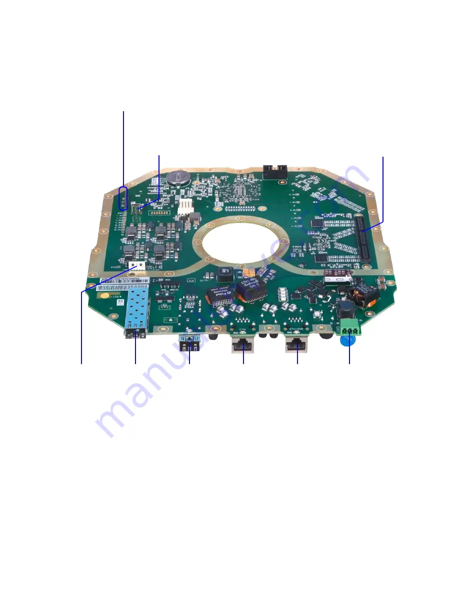
SPU Description.
1.1
Service connectors
SFP1
SFP2
LAN1
LAN2+POE
DC-IN
QSE (IQ) connector
USB MNG
Jumpers
USB
Storage
www.hypercable.fr www.e-rake.fr
[email protected]
Page 1: ...guration and trouble shooting information for the broadband wireless access outdoor radio TwinRadio HYC Wi 2000 Gigabit Full Duplex Radio Link 24 GHz XPIC FDD Radio PTP Bridge IP Link www hypercable f...
Page 2: ...nection and Login 12 3 2 General system configurations 13 3 3 IP configurations 14 3 4 Modem and Radio configurations 14 4 Graphical User Interface WEB GUI 15 4 1 Web header Side panel description 15...
Page 3: ...Graphs 31 4 8 5 Online Graphs 32 4 9 Maintenance Page 32 4 9 1 Config 32 4 9 2 Terminal 32 4 9 3 Files 32 4 9 4 Advanced 33 5 Command Line Interface CLI 35 5 1 Basic command structure 35 5 2 Altering...
Page 4: ...r 2 0 XPIC IP Link Page 4 of 39 Version 1 0 1 SPU Description 1 1 Service connectors SFP1 SFP2 LAN1 LAN2 POE DC IN QSE IQ connector USB MNG Jumpers USB Storage www hypercable fr www e rake fr info hyp...
Page 5: ...parate IP access to AOU unit A T the same time this port could be used for powering up of AOU unit over POE according to the standard LTPoE 90W All of 8 pins on the connector must be used pins 1 2 7 8...
Page 6: ...ult settings Follow these steps turn off the device and put a jumper to position FD Then turn on the device for about 15 seconds Turn off the device again and re move the jumper and then turn the devi...
Page 7: ...Link Page 7 of 39 Version 1 0 1 2 Status LEDs 1 3 Interface LED LED State Status SFP1 Link Off No Ethernet Link On Ethernet Link established Random Flashing Ethernet activity www hypercable fr www e r...
Page 8: ...e Status SPU status Orange Green On or Flashing LED indicators about the status of the device and its parts during the turn on process and while in operation SPU status during the device turn on proce...
Page 9: ...he right order FLED0 Off FPGA debugging LED there is no allocated function yet FLED1 Off FPGA debugging LED there is no allocated function yet FLED2 Off FPGA debugging LED there is no allocated functi...
Page 10: ...IP address In this case val id IP addresses are within range from 10 10 10 1 to 10 10 10 254 except for 10 10 10 10 Available access methods Method Port number Example WEB GUI interface 80 http 443 h...
Page 11: ...h belongs to the remote unit are indicated in an appropriate section header The re mote settings will be automatically transferred over internal management PPP connection to the remote unit This featu...
Page 12: ...updates reboot user administration USER user test View and change settings monitoring reboot GUEST guest no password View link related settings monitoring Interface Default primary secondary IP ETH PO...
Page 13: ...ossible roles ad min user and test each with their own set of privileges It is possible to alter the default Login Names and Passwords The device does not support adding another user defined user acco...
Page 14: ...of the link installation All radio related settings can be found in the GUI section Radio For initial link operation is necessary to set a T least these parameters TX Frequency The transmitting freque...
Page 15: ...this top bar section A content in this section is common to all GUI pages but can differ across different Modes Main Menu Main navigation menu which is accessible from each GUI page Device info sectio...
Page 16: ...lease note that it is recommended to save configuration and reboot the device after Mode change The available modes are end unit dual both channels will be used end unit 1 2 only the selected channel...
Page 17: ...in use 4 3 3 Users In this section you can define default credentials login name and password This page offers an option to accept only secure passwords For description of available login Roles please...
Page 18: ...lem with the device such as non working ventilator Modem SW A software problem such as incompatible mode selection on local and remote side Modem Sync This alarm indicates actual status of modem synch...
Page 19: ...vision and apply the remote settings Also note that you have to store any changed setting separately in both local and remote side RADIO TX Frequency Transmission frequency can be set within the displ...
Page 20: ...frequency Bandwidth the bandwidth of the transmitting modulation The number after the underscore indi cates the variant of the modulation Max RxACM Profile The highest possible modulation a T given ba...
Page 21: ...displayed as circular constellation points phase noise is displayed as rotationally spreading constellation points amplitude compression causes points located in the corner to move towards the centre...
Page 22: ...the powering into the radio part MODEM ADVANCED SETTINGS Modem Signal Type Specification of modulation output It is possible to replace standard modu lated signal with carrier signal CW in this drop d...
Page 23: ...otential loops a T connected LAN ports for all Modes The port settings consists of several configuration layers labelled leftmost of the configuration window PORT CONFIG Status status of a port as det...
Page 24: ...s limiting Speed Limit example Suppose the Available Speed is 110Mbps with ETH1a Speed Limit set to 50Mbps and ETH1b Speed Limit set to 110Mbps That means ETH1a payload traffic will be 50Mbps independ...
Page 25: ...t groups can use the same MAC addresses without any collision in the internal ETH switch ATU table Default VLAN This parameter is configured automatically depending on records in the VTU table Default...
Page 26: ...ties 8 frames from Q3 4 frames from Q2 2 frames from Q1 and 1 frame from Q0 This approach prevents the lower priority frames from being starved out with only a slight delay to the higher priority fra...
Page 27: ...ay IP address is used by MNG CPU when connection outside of IP range defined in system routing table is required Such IP address must be a part of above mentioned routing ta ble Routing table can be c...
Page 28: ...to add change delete static routes or NAT records This is especially required for Out of band type of management access STATIC ROUTES Routed IP MASK the IP address from routed network and the appropri...
Page 29: ...id characters are a z A Z 0 9 _ IP Address Mask up to three IP addresses or subnets can be configured as permitted IP source for SNMP management access Please note that the Mask parameter is not optio...
Page 30: ...during the last second FEC Global Rate the ratio of FEC Uncorrected Errors FEC RX Blocks FEC Actual Rate same as above but for latest second only Uncorrected TLE time since last error number of second...
Page 31: ...s and appropriate subnet masks are assigned to this interface Rfi1 2 ppp point to point protocol type of interface which interconnects local MNG CPU with the remote side MNG CPU accessible through the...
Page 32: ...ck 4 9 2 Terminal Inbuilt terminal window for interacting with device s CLI Command Line Interface directly from GUI For CLI usage description please see the Command Line Interface CLI section of this...
Page 33: ...ng the WRITE button 2 gradually select all files in order as described above Please note that after uploading of the fwbase afw file the device performs automatic reboot 3 after successful boot login...
Page 34: ...0 minutes of continuous error state when the check box is selected It is recommended to disable this function during link configuration and installation FACTORY DEFAULT Restores the configuration of t...
Page 35: ...he device name set by command set descr name new_name _NE the informative prompt The convention is xxx_XXY prompt in reading mode xxx_XXY prompt in enable mode xxx_XX Z prompt indicating unsaved chang...
Page 36: ...d exit It is also possible to forcefully takeover the enable mode by means of command kill enable Example device_name_NN set descr name my_device try to change device s name no access not in enable mo...
Page 37: ...rad1 analyzer my start spectrum analyzer option my means fine analysis around CF atpc radio atpc parameters down power off radio part ok my_device_NE set rad1 atpc off atpc off on atpc on rxlevel min...
Page 38: ...event occurs in the device a SNMP trap with basic summary of such event is sent to all ad dresses specified in the Trap IP Address fields Then such trap can be accordingly processed by your NMS solut...
Page 39: ...Full Outdoor 2 0 XPIC IP Link Page 39 of 39 Version 1 0 Name 1 3 6 1 4 1 12654 1 5 1 1 2 3 sysFceBasCmdWr Value 4 startup www hypercable fr www e rake fr info hypercable fr...
Page 40: ...45 1 56 50 1 40 55 1 25 60 1 09 65 0 93 70 0 78 75 0 62 80 0 47 85 0 31 90 0 16 95 0 00 0 00 0 50 1 00 1 50 2 00 2 50 3 00 100 90 80 70 60 50 40 30 20 10 0 RSSI BNC RSSI RF level dB www hypercable fr...