background image


                                                                                                                                                Page 72

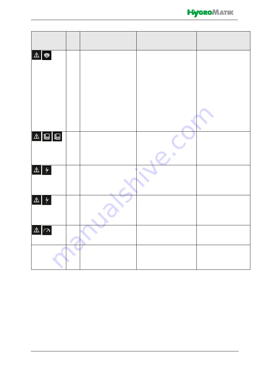
090

Cylinder full

Sensor electrode conti-
nously signals full cylinder 
for 60 mins

• 

Check blow-down pump, 

drainage system and steam 
cylinder for hardeners and 
clean

• 

Check feed water qual-

ity 

 Electrodes used up

• 

Replace electrodes

• 

No electrode cable run 

through current transducer

• 

Run one phase through 

current transducer

• 

Salt bridges in steamcylin-

der upper part

• 

Clean

• 

Foaming (when softened 

water is used)

• 

Increase blending rate

091

Current measurement

Current transducer sup-
plies faulty measurement

• 

Plug is not seated properly 

on main PCB

• 

Check plug seating

• 

Current transducer defec-

tive

• 

Replace current trans-

ducer

092

Main contactor current 

Current measured though 
the main contactor is not 
driven

• 

Main contactor contact 

sticks 

• 

Replace main contac-

tor

093

Main contactor cylinder 
full

„Cylinder full“ is detected 
though main contactor is 
not driven

• 

Main contactor contact 

sticks 

• 

Replace main contac-

tor

210

R.h. sensor

Humidity sensor signal 
implausibility

• 

Sensor cable defective 

• 

Check sensor cable

• 

Sensor defective

• 

Replace sensor

ErL

Error Link

no communication bet-
ween mainboard and dis-
play

• 

Mainboard or display unit 

defective

• 

Replace mainboard or 

display unit

Icons

Code

Error message

Possible cause

Counter measure

Summary of Contents for MiniSteam

Page 1: ...FlexLine Electrode Steam Humidifier Manual SLE ENO SLE EN E 8881152 StandardLine...

Page 2: ...the product or device No other right is granted under this licence In particular and without prejudice to the generality of the foregoing the Work s may not be used sold licensed transferred copied o...

Page 3: ...Construction 11 4 3 Operating sequence 12 5 Mechanical installation 13 5 1 Environment Parameters to be met and Mounting Recommendations 13 5 1 1 Dimensions and Mounting Directions 14 5 2 Unit Instal...

Page 4: ...fine filter and drain pump 38 9 3 4 Cleaning the vent hole on the pipe elbow 38 9 3 5 Reinstallation of the steam cylinder 39 9 4 Removal and installation of unit components 40 9 4 1 Blow down pump re...

Page 5: ...parameter descriptions 64 12 Trouble shooting 70 12 1 Error handling 70 12 1 1 Table of possible faults and related error codes 70 12 2 Table of functional disrup tions 73 13 Declaration of Conformit...

Page 6: ...documentation is manda tory for the operation of the unit This is not applicable to StandardLine devices here the documentation of the controller is included in the operation manual Retention Please r...

Page 7: ...s 2 1 and 2 2 in the section Detailed parameter descriptions in this manual Proper usage also comprises the adherence to the conditions specified by HygroMatik for installation dismantling reassembly...

Page 8: ...ult from it Cleaning and user maintenance of the unit must not be undertaken by children without supervision 2 1 3 Unit Operation Risk of scalding Uncontrolled hot steam escape in case of leaking or d...

Page 9: ...electrical voltage Any work on the electrical system to be per formed by certified expert staff electricians or expert personnel with comparable training only Steam operation may only be started when...

Page 10: ...y of Goods Upon receipt of the unit confirm that model and serial number on the name plate match those specified in the order and delivery documents the equipment is complete and all parts are in perf...

Page 11: ...Construction The StandardLine humidifiers are designed for wall mounting For maintenance pur poses the steam cylinders are separable in the middle Starting with the manufacturing date of 11 2018 the s...

Page 12: ...dic blow downs of some of the concentrated water are very important Following this procedure as rec ommended provides stable cylinder water conductivity as well as minimal water loss for the expected...

Page 13: ...rost may damage the steam cylinder the solenoid valve and pump as well as make hoses burst Relative humidity must not exceed 80 r h since values beyond may lead to electronic malfunction or dam age In...

Page 14: ...0 14 6 695 27 4 SLE45 SLE65 590 23 2 790 31 1 415 16 3 535 21 787 31 Detailed measurements under https www hygromatik com files pdf hygromatik standardline dimensionsv11 pdf 3D models under https www...

Page 15: ...y of the mounted screws hook in the unit and ensure safe suspension mark the holes for the lower suspen sion brackets screws remove the unit drill holes and dowel hook in the unit and mount the lower...

Page 16: ...Steam hose installed with a 5 10 minimum incline decline see chap ter Steam line Condensate hose features a loop functioning as a steam barrier see chapter Condensate hose Steam manifold s properly po...

Page 17: ...umidification t2 in C with steam humidifiers the change in air temperature due to humidification may be disregarded t1 or t2 Specific increase in humidity x in g kg can be determined in the h x diagra...

Page 18: ...Page 18 5 3 2 Absorption Distance Nomogram Source Henne Erich Luftbefeuchtung Air Humidification 3rd Edition 1984 Page 101 Olden bourg Industrieverlag Munich...

Page 19: ...m may possibly be required depending on the overall pres sure situation These modifications must be coordinated with your expert dealer Water drain We point out that according to the Ger man Associati...

Page 20: ...m manifold laterally staggered with respect to air flow direction in case of Lmin s above not to be met very flat by tilting the steam manifold 30 45 towards the air flow direction the mini mum upper...

Page 21: ...into the air duct from below is also possible Standard manifold dimensions mm inch Special lengths on demand Number and size of the steam manifolds available as well as the nominal diameter of the rep...

Page 22: ...hose installation Pressure conditions within the duct are influenced by device steam output steam line layout and the duct composition itself In some rare situations it may become necessary to optimi...

Page 23: ...below device upper edge In this arrangement the condensate hose cannot be fed back to the steam humidifier Run steam hose to a height of 400 mm 16 mm minimum above the steam humidifier and then to th...

Page 24: ...drain freely As installation or retrofit option the DVGW conform HyFlow system sepa rator is available for the HygroMatik electrode steam humidifiers except SLE 02 You can also use a standard BA CA s...

Page 25: ...lectrode and trigger the max level status message despite the cylin der not being full yet and the nominal current not yet established With softened water at operating tempera ture conductivity level...

Page 26: ...is reliably fas tened and wastewater can drain freely and pressureless Humidifier installation location and wastewa ter discharge must be on the same pressure level In case of a drain connection on po...

Page 27: ...pump drain hose jacket and the inner surface of the cabinet drain connection a gap exists due to the diverging diameters If water collects on the base plate it will flow through this gap into the dra...

Page 28: ...rostatical dis charge Prior to commencing electrical installation work steps must be taken to guard the sensi tive electronical components of the unit con trol against damage from electrostatical disc...

Page 29: ...y interlock open Install contact interlocks e g a max hygrostat vane relays pressure controllers air interlock devices etc in series across ter minal 1 and 2 Contacts across terminals 1 and 2 must be...

Page 30: ...an external supply voltage For that purpose terminal 3 has a 20 VDC offering 7 4 3 Wiring for control signal and safety interlock system for multiple units In the case of multiple units separate humid...

Page 31: ...ents and local power supply regulations Safety interlock properly wired across terminals 1 and 2 Supply voltage in accordance with name plate voltage rating All ectrical connections made according to...

Page 32: ...test and then commences normal operation During self test the display flashes for a couple of seconds On completion of the test the software version is displayed for a short moment Consequently norma...

Page 33: ...ing the steam cylinder inside and a unit test run Steam humidifier electrodes are prone to burn off during steam production and must consequently be replaced in a regular time frame As part of the mai...

Page 34: ...r expert dealer If the water quality differs this could result in a more frequent need for maintenance Cycle time Maintenance work 4 weeks after commissioning also after installa tion of a new steam c...

Page 35: ...cool down Check the temperature by carefully approaching it with your hand do not touch the cylinder if the rest heat should be too strong Remove Super Flush solenoid hose from cylinder bottom if app...

Page 36: ...of eye injuries The clips that fix the steam cylinder halves have sharp edges and can jump off during dismantling Eye injuries are possible Wear proper PPE Personal Protection Equipment Remove the cy...

Page 37: ...them off Replace the O rings of the elec trodes Install new electrodes 48 Make sure that the electrodes are positioned cor rectly see exploded view The deposits in the upper part of the cylinder can b...

Page 38: ...connections if necessary Remove the fine filter on the water connection side from the solenoid valve and clean it under running water Clean the drain pump as described in the section of the same name...

Page 39: ...t sit on their respective contacts as far as they will go Check electrode plugs for corro sion Replace if stained Risk of functional disruption Risk of material damage Loose cable connections may resu...

Page 40: ...r base 37 Open the pump bayonet lock Remove residues from pump and drain hoses Remove the used o Ring 33 Reinstallation Moisten the new O ring 33 and insert into cylinder base 37 hori zontal stub Push...

Page 41: ...and open it see also chapter Removal of the steam cylinder When mounting the electrodes make sure that the hand nut colours corresponding with the wiring colours remain in the same posi tion as befor...

Page 42: ...on composition and conductivity of the supply water the amount of steam produced In case of the electrodes being burned off to less than one third to half of their genuine length electrode replacemen...

Page 43: ...Follow the instructions in the section funktional check 9 6 Functional check Run the system with maximum out put for a couple of minutes Check hose connections and seals for leakage 9 7 Finishing main...

Page 44: ...humidifier is made up of metal parts and plastic parts In reference to European Union directive 2012 19 EU issued on 4 July 2012 and the related national legislation please note that The components o...

Page 45: ...f top head rail relays is available for the plugable con nection to the mainboard With heater type steam humidifier the power is controlled via a single phase or two phase solid state relay for device...

Page 46: ...steam cylin der minimum water level control For heater element protection and thermical overload risk avoidance no heater element drive ena bling is issued in case of minimum water level underrun Intr...

Page 47: ...12 6FKOLHVVHU RQWDFW j IHUPHWXUH 1 gIIQHU RQWDFW j RXYHUWXUH UHOD FROOHFWLYH IDXOW 5HODLV 6DPPHO VW UXQJ 5HODLV DYHUWLVVHXU 2KP 7HUPLQDOV OHPPHQ RQQHFWHXUV 67 P 9 9 1 9 67 67 9 9 RXWSXW 1 67 7 FXUUHQ...

Page 48: ...67 1 67 67 67 9ROWDJH DFFRUGLQJ QDPH SODWH 6SDQQXQJ JHPl 7 SHQVFKLOG 7HQVLRQ FRQIRUPpPHQW j OD SODTXH G LGHQWLILFDWLRQ 8VH FRSSHU FRQGXFWRUV RQO VL H DFFRUGLQJ FXUUHQW YDOXH RQ WKH QDPH SODWH HLWXQJV...

Page 49: ...OHPPHQ RQQHFWHXUV 67 P 9 9 1 9 67 67 9 9 RXWSXW 1 67 7 FXUUHQW WUDQVGXFHU 5LQJPHVV ZDQGOHU 7UDQVGXFWHXU PDLQ FRQWDFWRU DXSWVFK W RQWDFWHXU SULQFLSDO 0 GUDLQ SXPS EVFKOlPP SXPSH 3RPSH GH YLGDQJH VROHQR...

Page 50: ...SODWH 6SDQQXQJ JHPl 7 SHQVFKLOG 7HQVLRQ FRQIRUPpPHQW j OD SODTXH G LGHQWLILFDWLRQ 8VH FRSSHU FRQGXFWRUV RQO VL H DFFRUGLQJ FXUUHQW YDOXH RQ WKH QDPH SODWH HLWXQJVTXHVFKQLWW JHPl 6WURPDQJDEHQ DXI GHP...

Page 51: ...on with screw terminal adaptor for L and N power connection and safety interlock Terminals 1 2 Inputs ST09 only for heater steam humidifiers Filling level sensor ST09 only for electrode steam humidifi...

Page 52: ...accessed by pressing any key on the control panel On user level among other information reading values r01 to r15 are available After a certain time span with no keystroke control switches the dis pl...

Page 53: ...5 1 Control 2 Blow down 3 Service 4 Governing 5 Functions 6 Settings 2 only when imperial system was selected 3 only when PI controller was selected 4 only shown after code 10 input 5 direct access wh...

Page 54: ...for outputting of operational and input data as well as error code presentation When control software expects an input the digits are blinked Display semantics are determined by lightening up of one...

Page 55: ...upports changing of the parameters s next section This function is not meant for usage by the steam humidifier user PAr ist only presented when a 10 was input as the P00 setting value for access to pr...

Page 56: ...tory set ting Submenu Control Group1 Fs Factory setting Reading value index Description r01 Status r02 Fault r03 Actual steam output kg h r04 Actual steam outpt lb h only when imperial units were sele...

Page 57: ...out K1 only for electrode steam humidifiers 0 no 1 yes Fs 0 10 2 9 Steam down time only for heater steam humidifiers 0 250 WV 240 10 Par Denomination Setting options Code 3 1 Reset service interval st...

Page 58: ...e off 30 filling off 31 filling on 37 HyCool 60 Blow down off 61 Blow down on 62 Partial blow down 63 Full blow down 66 max level 67 Stand by blow down 68 Dead leg flushing 69 Start up blow down 270 C...

Page 59: ...yness Using the keys change the display to 10 Press the SET key Provider level is now entered 1 is displayed as the first parameter group to be changed Since the parameter to be changed is in this gro...

Page 60: ...s produced when demand is generated by a Hygrostat or an external controller With a PI con troller setting an input signal from the active humid ity sensor is required Safety interlock must be closed...

Page 61: ...w down icon in the display is lit 65 Max level only for heater steam humidifi ers Max allowable water level in steam cylinder was overrun 66 Stand by blow down In case of a safety interlock open for a...

Page 62: ...codes are described in the Trouble shooting chapter of this manual r03 Actual steam output SI units Amount of current steam production value kg h r04 Actual steam output imperial units Amount of curre...

Page 63: ...value Explanation P00 Code level Allows provider level access by code input Code 10 or limitation to user level Code 0 Provider level is exited automatically after 10 mins without a keystroke PAr Para...

Page 64: ...input stages This parameter allows for an active humidity sensor cali bration in the range from 5 r h to 5 r h Using this parameter you can calibrate the active humidity sensor at terminals 3 5 in a r...

Page 65: ...ameter 2 6 and for the duration of time preset in 2 7 In order for this to work the safety interlock must be closed 2 6 Interval dead leg flushing Waiting time h when there is no steam production unti...

Page 66: ...ation is not disrupted Service rate highly depends on water quality conductiv ity hardness and on the amount of steam produced since the last service By varying parameter 3 3 the ser vice interval may...

Page 67: ...relay is energized when a certain oper ating status occurs Factory setting is 0 defined as col lective fault It is activated if certain operational conditions apply The operational condition collectiv...

Page 68: ...ntactor K1 switching cycles is active 5 5 Relay_K20 allocation Defines logical function of the optional relay K20 in the same way as 5 4 does for the basic relay Factory pre set is 270 Collective serv...

Page 69: ...pt 6 2 Time Out Unit control switches the display back to actual steam output presentation after the time set in 6 2 Factory set ting is 2 minutes 6 3 Imperial units This parameter enables a switch be...

Page 70: ...d or loose Check plug 022 Input_current_min The min value of the input signal is no plausibel Sensor wiring or signal source defective Check sensor wiring and signal source if relevant Input stage def...

Page 71: ...cylinder and pushes water towards drain Check steam hose lay out Eliminate water bag L3 phase break down Main contactor does not switch L3 phase Reestablish L3 phase feeding Replace main contac tor 06...

Page 72: ...not seated properly on main PCB Check plug seating Current transducer defec tive Replace current trans ducer 092 Main contactor current Current measured though the main contactor is not driven Main co...

Page 73: ...rameter setting Water quality requires water concentra tion for full steam output Wait Excessive pressure in duct system caused by e g water bags or partly blocked steam pipes max overpressure is 1200...

Page 74: ...odes exist but no wa ter is fed into the cylinder Water supply not opened or solenoid valve electrically not driven Open water supply s also Fill ing fault messages 030 No steam produc tion despite th...

Page 75: ...eck main contactor Replace if required Ensure power supply phase ba lance by measurement Check installation and correct positioning if required Flashover sparks in cylinder Very high water conductivit...

Page 76: ...Page 76 13 Declaration of Conformity...

Page 77: ...nge clamps set 24pcs 37 1 1 E 3220002 Cylinder base 37 1 1 1 1 1 E 2206090 Cylinder base 1 1 B 2214023 Mounting set for cylinder base 1 1 1 1 1 B 3216023 Mounting set for cylinder base 1 E 3221000 Ada...

Page 78: ...1 1 WR 03 00001 Connecting cables for electrodes and sensor electrode with plugs 4 1 1 WR 04 00001 Connecting cables for electrodes and sensor electrode with plugs 4 1 WR 04 00101 Connecting cables fo...

Page 79: ...Page 79 This page intentionally left blank...

Page 80: ...Page 80 This page intentionally left blank...

Page 81: ...0 Operation weight kg 12 5 75 2 77 2 Width 9 mm Height 9 mm 375 Depth 9 mm Water connection Drain water connection 1 Other voltages upon request 3 Internal control voltage upon request 6 Incl Y piece...

Page 82: ...Page 82 16 Exploded view The number of steam outlets and the size of their connections can be found in the technical data...

Page 83: ...Page 83 17 View of housing This figure shows an example of one of the smaller unit sizes of the StandardLine series 70 56 57...

Page 84: ...Ein Unternehmen der Gruppe 100 Lise Meitner Str 3 D 24558 Henstedt Ulzburg Phone 49 0 4193 895 0 Fax 33 eMail hy hygromatik de www hygromatik com member of CAREL Group...

Reviews: