109
PW / PY Series
HOW TO USE THIS MANUAL
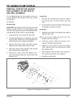
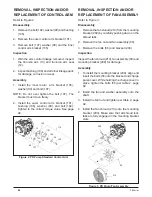
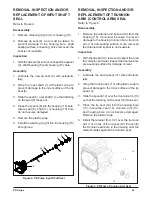
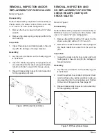
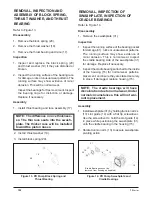
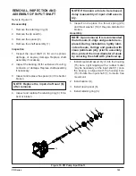
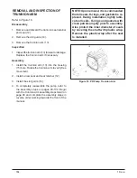
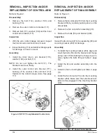
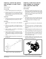
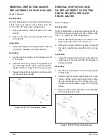
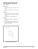
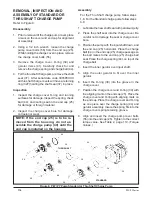
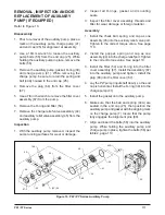
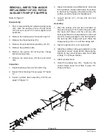
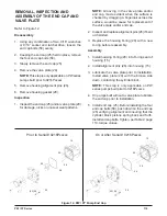
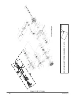
Each assembly is provided with an exploded
view showing the parts involved.
The item
reference numbers in each illustration are for
assembly instructions only.
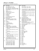
See pages 124 and
125 for part names and descriptions. A complete
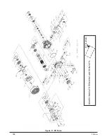
exploded view and item list of the pump is provided
at the end of this section.
GENERAL INSTRUCTIONS
Cleanliness is a primary means of ensuring
satisfactory life on repaired pumps. Thoroughly
clean all exposed surfaces prior to any type of main-
tenance. Cleaning of all parts by using a solvent
wash and air drying is usually adequate. As with any
precision equipment, all parts must be kept free of
foreign material and chemicals.
Protect all exposed sealing surfaces and open
cavities from damage and foreign material. The
external surfaces should be cleaned before
beginning any repairs.
Lip-type seals (shaft seals) are used on the input
shaft and directional control shaft of each Pump.
These seals can be replaced without major disas-
sembly of the unit. However, replacement of these
seals generally requires removal of the pump from
the machine. Upon removal, it is recommended that
all seals, O-rings and gaskets be replaced.
During installation, lightly lubricate all seals,
O-rings and gaskets with clean petroleum jelly prior
to assembly. Also protect the inner diameter of the
seals by covering the shaft with a cellophane (plastic
wrap, etc.) material.
Parts requiring replacement must be replaced from
the appropriate kits identified in the Items Listing,
found at the end of this manual. Use only original
Hydro-Gear replacement parts found listed in BLN-
51427 (CD).
REPAIR - PW / PY SERIES PUMP
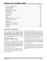
Repair - PW / PY Series Pump .......................................................................................... 109-126
How to Use This Manual............................................................................................................109
General Instructions
..................................................................................................................109
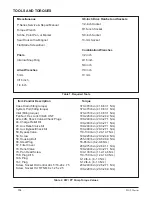
Tools and Torques .....................................................................................................................110
Return to Neutral Linkage .......................................................................................................... 111
Standard Control Arm Linkage ..................................................................................................112
Fan Assembly ............................................................................................................................112
Input Shaft Seal
.........................................................................................................................113
Trunnion Arm Seal .....................................................................................................................113
Check Valves .............................................................................................................................114
Shock Valves .............................................................................................................................114
Bypass .......................................................................................................................................115
Charge Pump-Standard or Thru Shaft .......................................................................................116
Auxiliary Pump ...........................................................................................................................117
Auxiliary Pump (6cc Piston).......................................................................................................118
End Cap .....................................................................................................................................119
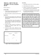
Cylinder Block ............................................................................................................................120
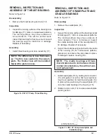
Block Spring and Thrust Bearings .............................................................................................121
Swashplate and Cradle Bearings ..............................................................................................121
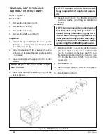
Input Shaft
.................................................................................................................................122
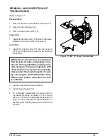
Trunnion Arm .............................................................................................................................123
Parts List ............................................................................................................................ 124-125
Summary of Contents for HGM-H Series
Page 1: ...BLN 0043 January 2018 HGM H Series Motor Service and Repair Manual ...
Page 25: ...24 HGM H HGM H MOTOR EXPLODED VIEW ...
Page 29: ...HEMTM Series Motor Service and Repair Manual BLN 0083 January 2018 ...
Page 52: ...PRM MOTOR Service and Repair Manual ...
Page 56: ...PRM 3 EXTERNAL FEATURES PRM MOTOR Figure 1 PRM External Features ...
Page 77: ...24 PRM SECTION 8 PARTS LIST Figure 48 MA04K030 ...
Page 81: ...BLN 50231 January 2018 BDP 10L PL Hydrostatic Pump Service and Repair Manual ...
Page 82: ......
Page 83: ......
Page 84: ......
Page 85: ......
Page 86: ......
Page 87: ......
Page 88: ......
Page 89: ......
Page 90: ......
Page 91: ......
Page 92: ......
Page 95: ......
Page 96: ......
Page 97: ......
Page 98: ......
Page 99: ......
Page 100: ...HGM 12P LSHT Wheel Motor Service and Repair Manual BLN 52197 January 2018 ...
Page 102: ...2 Exploded view HGM P ...
Page 117: ...HGM E LSHT Wheel Motor Service and Repair Manual BLN 52198 January 2018 ...
Page 144: ...2 P Series EXTERNAL FEATURES PC SERIES Figure 1 PC Pump with Standard Charge Pump ...
Page 146: ...4 P Series EXTERNAL FEATURES PJ SERIES Figure 3 PJ Pump with Standard Charge Pump ...
Page 147: ...5 P Series Figure 4 PK Pump With Standard Charge Pump EXTERNAL FEATURES PK SERIES ...
Page 176: ...34 PC Series Figure 16 PC Pump BOXES INDICATE ITEMS INCLUDED IN Kit Number ...
Page 192: ...52 PG PE Series Figure 17 PG PE Pump BOXES INDICATE ITEMS INCLUDED IN KITS Kit Number ...
Page 208: ...70 PJ Series Figure 17 PJ Pump BOXES INDICATE ITEMS INCLUDED IN Kit Number ...
Page 224: ...88 PK Series Figure 17 PK Pump BOXES INDICATE ITEMS INCLUDED IN Kit Number ...
Page 240: ...106 PR Series Figure 17 PR Pump BOXES INDICATE ITEMS INCLUDED IN KITS Kit Number ...
Page 261: ...HGM C LSHT Wheel Motor Service and Repair Manual BLN 52690 January 2018 ...

