100
PR Series
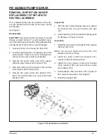
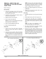
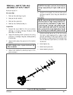
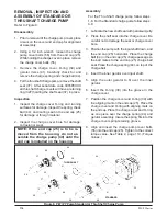
Refer to Figure 11.
Disassembly
1. Using any combination of two, 9/16” wrenches
or 9/16” socket and ratchet drive, loosen the
end cap bolts (58) evenly.
2. Keeping the end cap (25) held in place, remove
the four end cap bolts (58).
3. Slowly remove the end cap (25).
4. Remove the valve plate (29).
NOTE:
This step is only applicable on PR series
pumps built prior to 0216Pxxxxx.
5. Remove housing alignment pins (26).
6. Remove housing gasket (28).
Inspection
1. Inspect the end cap (25) body for damage,
nicks or unusual wear patterns. Replace if
necessary.
2. Inspect the running surface (side that contacts
the cylinder block) of the valve plate (29) and/
or end cap (25). The running surface may
show evidence of minor abrasive rings, this is
normal.
NOTE:
Grooving in the valve plate and/or end
cap, made evident when the surface is checked
by dragging a fingernail across it, would be
cause for replacement of the valve plate.
3. Inspect and replace alignment pins (26) if bent
or distorted.
4. Replace the housing O-ring (28) with a new
O-ring before reassembly.
Assembly
1. Install O-ring (28) into the O-ring seat of housing
(15).
2. Install alignment pins (26) into housing (15).
3. Lubricate the valve plate prior to installation.
Install valve plate (29) so the bronze side of the
valve plate is facing down toward the cylinder
block.
NOTE:
This step is only applicable on PR
series pumps built prior to 0216Pxxxxx.
4. On pumps built without a valve plate, lubricate
the end cap (25) prior to installation.
5. Install end cap (25). Before installing the four
end cap bolts (58), push down on the end cap
(25) verifying alignment and insuring that the
cylinder block pistons spring back and forth.
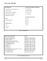
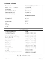
Install and torque end cap bolts (58). Reference
Table 2, page 92 (torque values).
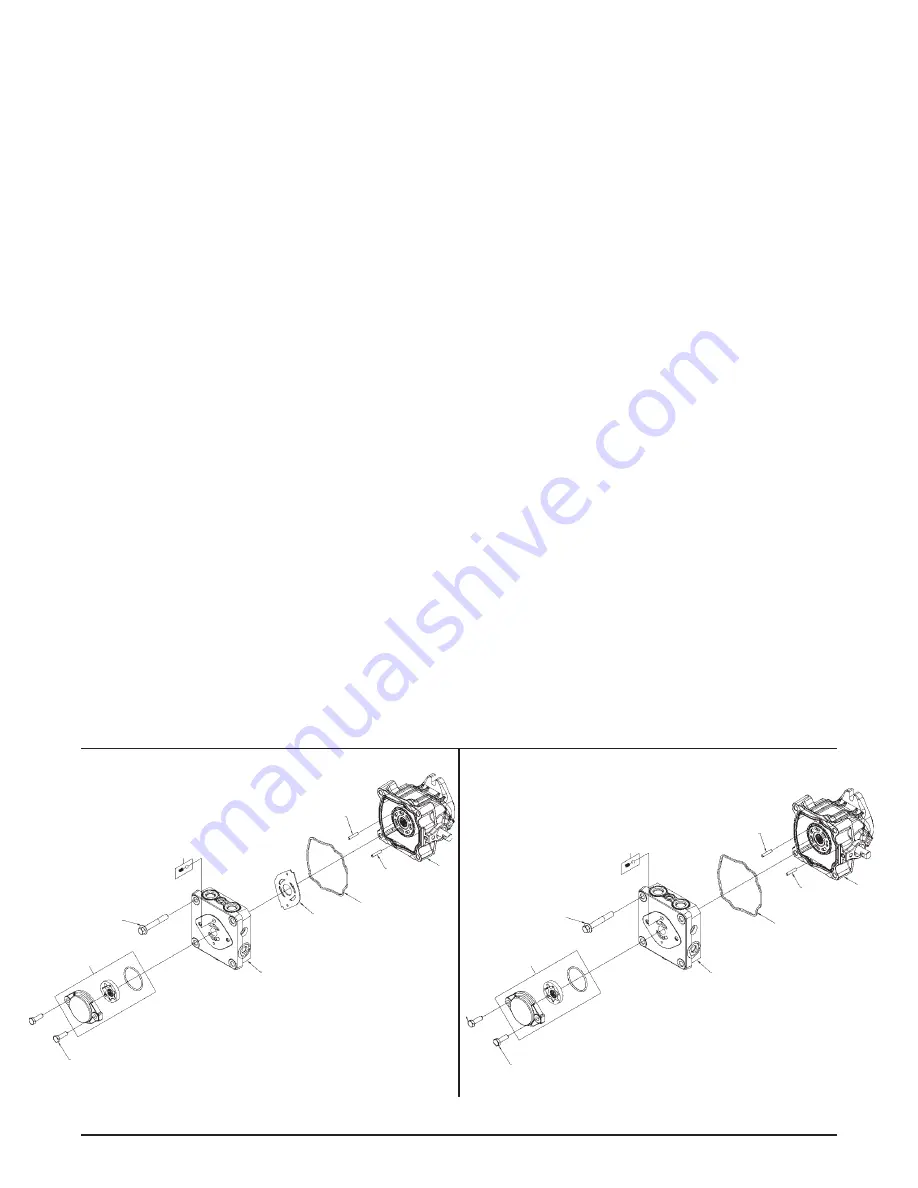
REMOVAL, INSPECTION AND
ASSEMBLY OF THE END CAP AND
VALVE PLATE
Figure 11. PR Pump End Cap
56
40
4X 58
25
29
28
26
26
15
44
56
40
4X 58
25
28
26
26
15
44
Prior to Serial # 0216Pxxxxx
On or After Serial # 0216Pxxxxx
Summary of Contents for HGM-H Series
Page 1: ...BLN 0043 January 2018 HGM H Series Motor Service and Repair Manual ...
Page 25: ...24 HGM H HGM H MOTOR EXPLODED VIEW ...
Page 29: ...HEMTM Series Motor Service and Repair Manual BLN 0083 January 2018 ...
Page 52: ...PRM MOTOR Service and Repair Manual ...
Page 56: ...PRM 3 EXTERNAL FEATURES PRM MOTOR Figure 1 PRM External Features ...
Page 77: ...24 PRM SECTION 8 PARTS LIST Figure 48 MA04K030 ...
Page 81: ...BLN 50231 January 2018 BDP 10L PL Hydrostatic Pump Service and Repair Manual ...
Page 82: ......
Page 83: ......
Page 84: ......
Page 85: ......
Page 86: ......
Page 87: ......
Page 88: ......
Page 89: ......
Page 90: ......
Page 91: ......
Page 92: ......
Page 95: ......
Page 96: ......
Page 97: ......
Page 98: ......
Page 99: ......
Page 100: ...HGM 12P LSHT Wheel Motor Service and Repair Manual BLN 52197 January 2018 ...
Page 102: ...2 Exploded view HGM P ...
Page 117: ...HGM E LSHT Wheel Motor Service and Repair Manual BLN 52198 January 2018 ...
Page 144: ...2 P Series EXTERNAL FEATURES PC SERIES Figure 1 PC Pump with Standard Charge Pump ...
Page 146: ...4 P Series EXTERNAL FEATURES PJ SERIES Figure 3 PJ Pump with Standard Charge Pump ...
Page 147: ...5 P Series Figure 4 PK Pump With Standard Charge Pump EXTERNAL FEATURES PK SERIES ...
Page 176: ...34 PC Series Figure 16 PC Pump BOXES INDICATE ITEMS INCLUDED IN Kit Number ...
Page 192: ...52 PG PE Series Figure 17 PG PE Pump BOXES INDICATE ITEMS INCLUDED IN KITS Kit Number ...
Page 208: ...70 PJ Series Figure 17 PJ Pump BOXES INDICATE ITEMS INCLUDED IN Kit Number ...
Page 224: ...88 PK Series Figure 17 PK Pump BOXES INDICATE ITEMS INCLUDED IN Kit Number ...
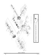
Page 240: ...106 PR Series Figure 17 PR Pump BOXES INDICATE ITEMS INCLUDED IN KITS Kit Number ...
Page 261: ...HGM C LSHT Wheel Motor Service and Repair Manual BLN 52690 January 2018 ...

