19
P Series
FLUID VOLUME AND LEVEL
Certain situations may require additional fluid to
be added or even replaced. Refer to the vehicle
manufacturer’s recommendations for the proper fill
location and level. After maintenance or oil change,
follow purging procedures below and check the
fluid level once the unit has been operated for ap
-
proximately 1 minute.
FLUID CHANGE
In the event of oil contamination or degradation,
oil addition or change may alleviate certain per-
formance problems. Refer to the vehicle manufac-
turer’s recommended oil change frequency. Refer to
purging procedures below after changing fluids.
FILTERS
An inlet filter is required to insure that only clean fluid
enters the system. Refer to the vehicle manufacture
for approved filter replacement.
PURGING PROCEDURES
Due to the effects air has on efficiency in hydrostatic
drive applications, it is critical that air is removed or
purged from the system.
These purge procedures must be preformed any-
time a hydrostatic system has been opened for
maintenance or repair, or if any additional oil has
been added to the system.
Air creates inefficiency because it has compres
-
sion and expansion rates that are higher than that
of oil.
Air trapped in the oil may cause the following
symptoms:
1. Noisy operation.
2. Lack of power or drive after short-term
operation.
3. High operation temperature and excessive
expansion of oil.
Before starting, make sure the reservoir is at the
proper oil level. If it is not, fill to the vehicle manu
-
facturer’s specifications.
The following procedures should be performed
with the vehicle drive wheels off the ground, then
repeated under normal operating conditions.
WARNING
POTENTIAL FOR SERIOUS INJURY
Certain procedures require the vehicle
engine to be operated and the vehicle to
be raised off of the ground. To prevent
possible injury to the servicing techni-
cian and/or bystanders, insure the ve-
hicle is properly secured.
1. With the bypass valve open and the engine
running, slowly move the directional control
in both forward and reverse directions (5 to 6
times). As air is purged from the unit, the oil level
in the reservoir will drop.
2. With the bypass valve closed and the engine
running, slowly move the directional control
in both forward and reverse directions (5 to
6 times). Check the oil level, and add oil as
required after stopping engine.
3. It may be necessary to repeat steps 1 and
2 until all the air is completely purged from
the system. When the P Series Pump moves
forward and reverse at normal speed and the
reservoir oil remains at a constant level, purging
is complete.
Cleanliness is a key factor in the successful repair of
pumps. Thoroughly clean all exposed surfaces prior
to any type of maintenance. Cleaning of all parts
by using a solvent wash and air drying is usually
adequate. As with any precision equipment, all parts
must be kept free of foreign material and chemicals.
Protect all exposed sealing areas and open cavities
from damage and foreign material.
Upon removal, all seals, O-rings, and gaskets
should be replaced. During installation, lightly lu-
bricate all seals, O-rings, and gaskets with clean
petroleum jelly prior to assembly. Also protect the
inner diameter of seals by covering the shaft ma-
chined features with plastic wrap or equivalent.
Note: “Any and all Hydro-Gear com-
ponents removed and replaced during
service are recyclable.”
Summary of Contents for HGM-H Series
Page 1: ...BLN 0043 January 2018 HGM H Series Motor Service and Repair Manual ...
Page 25: ...24 HGM H HGM H MOTOR EXPLODED VIEW ...
Page 29: ...HEMTM Series Motor Service and Repair Manual BLN 0083 January 2018 ...
Page 52: ...PRM MOTOR Service and Repair Manual ...
Page 56: ...PRM 3 EXTERNAL FEATURES PRM MOTOR Figure 1 PRM External Features ...
Page 77: ...24 PRM SECTION 8 PARTS LIST Figure 48 MA04K030 ...
Page 81: ...BLN 50231 January 2018 BDP 10L PL Hydrostatic Pump Service and Repair Manual ...
Page 82: ......
Page 83: ......
Page 84: ......
Page 85: ......
Page 86: ......
Page 87: ......
Page 88: ......
Page 89: ......
Page 90: ......
Page 91: ......
Page 92: ......
Page 95: ......
Page 96: ......
Page 97: ......
Page 98: ......
Page 99: ......
Page 100: ...HGM 12P LSHT Wheel Motor Service and Repair Manual BLN 52197 January 2018 ...
Page 102: ...2 Exploded view HGM P ...
Page 117: ...HGM E LSHT Wheel Motor Service and Repair Manual BLN 52198 January 2018 ...
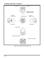
Page 144: ...2 P Series EXTERNAL FEATURES PC SERIES Figure 1 PC Pump with Standard Charge Pump ...
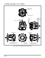
Page 146: ...4 P Series EXTERNAL FEATURES PJ SERIES Figure 3 PJ Pump with Standard Charge Pump ...
Page 147: ...5 P Series Figure 4 PK Pump With Standard Charge Pump EXTERNAL FEATURES PK SERIES ...
Page 176: ...34 PC Series Figure 16 PC Pump BOXES INDICATE ITEMS INCLUDED IN Kit Number ...
Page 192: ...52 PG PE Series Figure 17 PG PE Pump BOXES INDICATE ITEMS INCLUDED IN KITS Kit Number ...
Page 208: ...70 PJ Series Figure 17 PJ Pump BOXES INDICATE ITEMS INCLUDED IN Kit Number ...
Page 224: ...88 PK Series Figure 17 PK Pump BOXES INDICATE ITEMS INCLUDED IN Kit Number ...
Page 240: ...106 PR Series Figure 17 PR Pump BOXES INDICATE ITEMS INCLUDED IN KITS Kit Number ...
Page 261: ...HGM C LSHT Wheel Motor Service and Repair Manual BLN 52690 January 2018 ...

