20
P Series
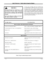
RETURN TO NEUTRAL SETTING
WARNING
POTENTIAL FOR SERIOUS INJURY
Inattention to proper safety, operation, or
maintenance procedures could result in
personal injury, or damage to the equip-
ment. Before servicing or repairing the P
Series Pump, fully read and understand
the safety precautions described in this
manual.
The return to neutral mechanism on the pump is
designed to set the directional control into a neutral
position when the operator releases the vehicle
hand control. Follow the procedures below to
properly adjust the return to neutral mechanism on
the pump:
1. Confirm the pump is in the operating mode
(bypass disengaged). Raise the vehicle’s drive
tires off the ground to allow free rotation.
2. Remove the Original Equipment Manufacturer’s
(OEM’s) control linkage at the control arm.
3. Start the engine and increase the throttle to full
engine speed.
WARNING
Do not attempt any servicing or ad-
justments with the engine running.
Use extreme caution while inspecting
the drive belt assembly and all vehicle
linkage!
Follow all safety procedures outlined in
the vehicle owner’s manual.
4. Check for axle rotation. If the axle does not
rotate, go to Step 5. If the axle rotates, go to
Step 6.
5. Stop the vehicle’s engine. Reattach and adjust
the vehicle’s linkage according to the vehicle
owner’s manual.
6. Note the axle directional movement. Stop the ve-
hicle engine. Loosen the RTN adjustment screw
until the control arm can be rotated. Rotate the
control arm in the proper direction until neutral is
obtained (motor shaft does not rotate). Tighten
the RTN adjustment screw. Recheck according
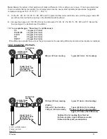
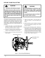
to steps 3 and 4. Refer to Figure 12.
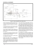
Figure 17. P Series Pump RTN Adjustment
RTN Adjusting Screw
Speed & Direction
Control Arm
Summary of Contents for HGM-H Series
Page 1: ...BLN 0043 January 2018 HGM H Series Motor Service and Repair Manual ...
Page 25: ...24 HGM H HGM H MOTOR EXPLODED VIEW ...
Page 29: ...HEMTM Series Motor Service and Repair Manual BLN 0083 January 2018 ...
Page 52: ...PRM MOTOR Service and Repair Manual ...
Page 56: ...PRM 3 EXTERNAL FEATURES PRM MOTOR Figure 1 PRM External Features ...
Page 77: ...24 PRM SECTION 8 PARTS LIST Figure 48 MA04K030 ...
Page 81: ...BLN 50231 January 2018 BDP 10L PL Hydrostatic Pump Service and Repair Manual ...
Page 82: ......
Page 83: ......
Page 84: ......
Page 85: ......
Page 86: ......
Page 87: ......
Page 88: ......
Page 89: ......
Page 90: ......
Page 91: ......
Page 92: ......
Page 95: ......
Page 96: ......
Page 97: ......
Page 98: ......
Page 99: ......
Page 100: ...HGM 12P LSHT Wheel Motor Service and Repair Manual BLN 52197 January 2018 ...
Page 102: ...2 Exploded view HGM P ...
Page 117: ...HGM E LSHT Wheel Motor Service and Repair Manual BLN 52198 January 2018 ...
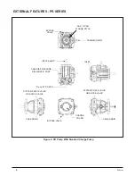
Page 144: ...2 P Series EXTERNAL FEATURES PC SERIES Figure 1 PC Pump with Standard Charge Pump ...
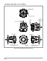
Page 146: ...4 P Series EXTERNAL FEATURES PJ SERIES Figure 3 PJ Pump with Standard Charge Pump ...
Page 147: ...5 P Series Figure 4 PK Pump With Standard Charge Pump EXTERNAL FEATURES PK SERIES ...
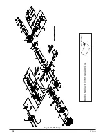
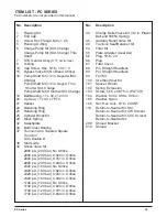
Page 176: ...34 PC Series Figure 16 PC Pump BOXES INDICATE ITEMS INCLUDED IN Kit Number ...
Page 192: ...52 PG PE Series Figure 17 PG PE Pump BOXES INDICATE ITEMS INCLUDED IN KITS Kit Number ...
Page 208: ...70 PJ Series Figure 17 PJ Pump BOXES INDICATE ITEMS INCLUDED IN Kit Number ...
Page 224: ...88 PK Series Figure 17 PK Pump BOXES INDICATE ITEMS INCLUDED IN Kit Number ...
Page 240: ...106 PR Series Figure 17 PR Pump BOXES INDICATE ITEMS INCLUDED IN KITS Kit Number ...
Page 261: ...HGM C LSHT Wheel Motor Service and Repair Manual BLN 52690 January 2018 ...

