Huvitz HOCT-1 User Manual Download Page 106


106 

9. 

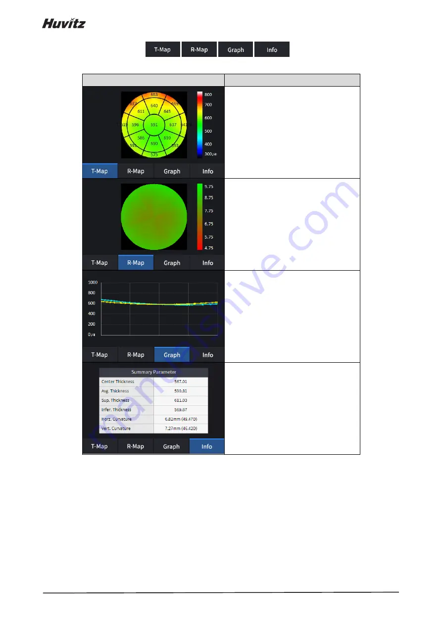
Select analysis tool icon(

,

,

,

) to show the analysis result. 


Analyze Screen 

Function 


-

 Displays thickness map. 


-

 Displays radius map. 


-

Displays 

thickness 

based  on  the 

previously set Thickness Layer. 

(EPI / EPI <-> END) 


-

 Displays following measured values. 

 
Center Thickness. 
Average Thickness. 
Superior Thickness. 
Inferior Thickness. 
Horizon Curvature. 
Vertical Curvature. 


Summary of Contents for HOCT-1

Page 1: ...OPTICAL COHERENCE TOMOGRAPHY HOCT 1 1F USER MANUAL...

Page 2: ...serves the right to make changes in its products or product specifications at any time and without prior notice and is not required to update this documentation to reflect such changes Revision Histor...

Page 3: ...6 Installation Procedure 28 5 1 System installation 28 Operation 31 6 1 Software 31 6 2 SETUP Mode 33 6 3 DICOM SETUP Mode 38 6 4 General Operation 40 6 5 Anterior segment image operation optional 53...

Page 4: ...4 8 2 Specifications 148 8 3 Drawings of System 149 EMC INFORMATION 150 SERVICE INFORMATION 152 SOFTWARE LICENSE AGREEMENTS 153...

Page 5: ...iately within the text of this manual to highlight safety related information or information requiring special emphasis All users operators and maintainers must be familiar with and pay particular att...

Page 6: ...endre la fonction de ce contr le avant de l utiliser La fonction de contr le est d crite dans le manuel d utilisation ou d entretien appropri I and O on power switch represent ON and OFF respectively...

Page 7: ...oduit est couvert par la directive europ enne 2002 96 CE Tous les produits lectriques et lectroniques doivent tre limin s s par ment du flux des d chets municipaux via des installations de collecte d...

Page 8: ...A specification compliance as follows Les tats Unis et le Canada ont conclu des accords de libre change Par cons quent si l on obtient une certification au moyen d une sp cification canadienne CSA pou...

Page 9: ...e of equipment in rated voltage less than 125Vac minimum 6A Type SJT or SVT 18 3AWG 10A max 3 0m long One end with Hospital Grade Type NEMA 5 15P Other end with appliance coupler For use of equipment...

Page 10: ...nce is just 15mm that the front lens is very close to patient s eye This instrument includes lithium battery This hazardous material needs to be disposed of properly to limit environmental pollution P...

Page 11: ...4 1 x 10⁷ sec for Kerato ring Auto Manual Tracking 9 5 x 10⁷ sec for Kerato focus Auto Manual Tracking 1 0 x 108 sec for Split focus Optimizing 9 1 x 10⁵ sec for external fixation lamp 4 8 x 10⁷ sec...

Page 12: ...e Optimal temperature range for normal operation is from 10 C to 35 C Humidity 30 90 Where there is hot equipment nearby Where the humidity is extremely high or there is a ventilation problem Where th...

Page 13: ...rotective earth For the normal operation of the instrument please keep the ambient temperature is 10 35 humidity is 30 90 and atmospheric pressure is 800 1060hpa For the Transportation of the instrume...

Page 14: ...evice to water splashes dripping water or sprayed water Do not place containers with fluids liquids or gases on top of this instrument 8 The instrument must be operated by a trained and qualified pers...

Page 15: ...contact customer service center 22 To avoid the risk of electric shock this instrument must only be connected to protective earth 23 Do not place the instrument where it is difficult to operate the d...

Page 16: ...or has a hand injury or a significant allergic reaction to the material used in the operation contact part Part Name Material LCD Touch pannel Glass Joystick button ABS Silicon Aluminum A6061 T6 Power...

Page 17: ...inopathy and aged related macular degeneration which are occurred at a macular an optic disk an inner structure of retina and a cornea 3 3 Classification Classification of product Class II according t...

Page 18: ...l a fundus tomogram can be formed 3 6 3 The angiography of a retina Optional To form retinal vessel maps the system main body scans several times at the same position and gets the same number of tomog...

Page 19: ...ng image 4 User Lock Lock for fixing body to base frame 5 OPT button Button for optimizing OCT signal 6 1 6 2 Align index mark Mark for indicating center of body and base 7 Base Power button Button fo...

Page 20: ...e 4 2 Mirering Focus LED LEDs for checking working distance 5 Headrest Objective lens cap Cap for protecting objective lens 8 Base External port Port for communicating internal or external device 8 1...

Page 21: ...HOCT 1 1F Bottom View No Part Name Description 1 Base Packing lock Lock for fixing body and base during transportation 2 points...

Page 22: ...eye OS left eye 4 AUTO S Show auto shooting selection status 5 AUTO T Show auto tracking selection status 6 FIXATION Select position of internal fixation target 7 C LENS Show compensation lens status...

Page 23: ...uring fundus image 18 Scan Start Start OCT scan Confirmation screen No Name Function 1 Image selection Decide validity of current image OK Save current image RETRY Discard current image and retry capt...

Page 24: ...OCT image 4 2 2 OCT mode Observation screen Refer 4 2 1 OCT Fundus mode Observation screen for uncommented item No Name Function 1 DISC T Tracking the best status with disc while scanning 2 Signal Lev...

Page 25: ...ed item 4 2 3 Fundus mode HOCT 1F only Observation screen Refer 4 2 1 OCT Fundus mode Observation screen for uncommented item No Name Function 1 Capture mode Select capture mode Single macular Capture...

Page 26: ...us image 3 Optimize Find focus position automatically by split focus image Confirmation screen Refer 4 2 1 OCT Fundus mode Confirmation screen for uncommented item No Name Function 1 Fundus informatio...

Page 27: ...een for uncommented item No Name Function 1 Disc tracking box Tracking the best status with disc box while scanning 2 Scan region It is sized with scan range Confirmation screen Refer 4 2 1 OCT Fundus...

Page 28: ...he two packing lock screw under the main body 3 Unscrew the user lock lever on the body 4 Attach two base packing lock cap while moving body left and right with joystick 5 Attach the chinrest paper to...

Page 29: ...ER BASE VENT with screw driver 8 Check the power switch on the bottom right of base is off O position 9 Connect power cable to power inlet Also connect the other side of power cable to electric outlet...

Page 30: ...pressing power button 14 Check there is no error during initialize process Wait for until the initialization is complete 15 Check the movement of body with joystick Also check the movement of motoriz...

Page 31: ...n 6 1 Software 1 Input user ID and password for login 2 Press resist patient icon and input patient information If patient is resisted already skip this step 3 Select patient and check patient informa...

Page 32: ...viewer or delete patient information select the circle next to the ID and press the TRANSFER icon or DELETE icon 5 When you select a patient the screen changes 6 Enter observation mode by pressing mea...

Page 33: ...hen this option is turned on the Light is turned on for convenient cleaning of the Objective Lens User Set User ID and Password for Login Auto Export Auto export setting Language Language setting 2 Pa...

Page 34: ...ethnicities have different conditions Small Pupil Guide Small Pupil Guide ON OFF setting Pupil Size Text Pupil Size Text ON OFF setting Fundus Compression Compress the fundus image qualities Show Fixa...

Page 35: ...ettings Scan Image Color Set the default representation mode of Bscan image to be either gray pseudo color or inversed gray Scan Image Level Adjust the gray level values of Bscan image Auto Chart Cent...

Page 36: ...e relative map Text color Set the measurement value text ruler value color 6 Report Settings Report Logo Add the Logo into report Report Brightness Set the brightness of report Report Type Set the rep...

Page 37: ...HOCT 1 1F 6 2 2 Angiography module setting 1 Click Angio button at SET UP Info page 2 Put in License Code and Click OK button 3 Then pop up the certification message window...

Page 38: ...where the server program is installed Server Port Set Port Number Server AE Set Server AE Client AE Set Client AE 2 MPPS Setting Server IP IP Address of the PC where the server program is installed Se...

Page 39: ...tting Manufacturer Set the name of the manufacturer Model Name Set the Model Name Institution Set the name of the institution Station Set the name of the Station Serial Number Set the Serial Number Tr...

Page 40: ...cotton swab or gauze Remove a single sheet of chinrest paper if the chinrest paper is used 2 Align left right index mark B and front index mark A of body and base with joystick 3 Let the patient sit...

Page 41: ...image 2 Set capture region with the capture region combo box OCT Fundus Macular Disc Anterior OCT Fundus Single Panorama 3 In OCT or OCT Fundus mode set scan type and options for the selected scan re...

Page 42: ...42 Scan along 24 lines in the square area centered at macular Scan a rectangular area closely Scan a rectangular area Scan along 12 radial lines centered at disc...

Page 43: ...HOCT 1 1F Scan along 24 lines in the square area centered at disc Scan a rectangular area closely Scan along a circle centered at optic disc Scan a rectangular area Scan along a line for cornea...

Page 44: ...uce one B scan image Possible options are enumerated Direction Set a direction which is horizontal or vertical Space Set an interval between neighboring scan lines Sensitivity Choose scan quality from...

Page 45: ...ans in the scan range 4 Set auto shooting mode Auto shooting is on Auto shooting is off If auto shooting mode is on image is optimized and captured automatically when aligned and focused to the patien...

Page 46: ...the focus with the focus slide bar manually 0 No compensation lens is used Minus compensation lens is used Plus compensation lens is used 7 Click the Scan Direction icon if you want to change the scan...

Page 47: ...ing of 8 white Mire dot B are concentric When two rings are concentric focus indicator bar C appears Move the body back and forth with joystick until the focus indicator bar disappears 2 If the pupil...

Page 48: ...ress scan start icon to start OCT scan If alignment and focus is in good condition scan start function is accomplished automatically and scan start icon changes to optimize icon 2 Optimize OCT signal...

Page 49: ...ge result too bright or too dark because of lighting regulate the flash intensity using flash icon in observation mode B If fundus image is too dark because of small pupil size of patient try small pu...

Page 50: ...scan position handle Check continuous OCT image continuously by pressing play image icon if needed Check SSI for image quality if needed SSI Scan Signal Index indicates level of image quality SSI mean...

Page 51: ...ion by pressing optimize icon on the screen or optimize button on the body A 2 Press the button on joystick to capture image If auto shooting is on 11 2 Optimize and 11 3 Capture is accomplished autom...

Page 52: ...y moving internal fixation target position by pressing fixation icon and changing position of green cross if needed When green cross position changes the position of internal fixation target is also c...

Page 53: ...Hang anterior headrest rubber to headrest of instrument C first then press anterior headrest rubber to be fixed firmly 5 Check the mounted anterior headrest rubber does not incline 6 5 2 Capturing an...

Page 54: ...icon Move body with joystick slowly until section of cornea appears on the screen 2 Measuring curvature of cornea Optimize OCT signal by pressing optimize icon on the screen or optimize button on the...

Page 55: ...ndus image result too bright or too dark because of lighting regulate the flash intensity using flash icon in observation mode B Try moving internal fixation target position by pressing fixation icon...

Page 56: ...ndicates level of image quality SSI means signal to background ratio and displayed on a scale of 10 with a bar graph SSI larger than 8 means Good 5 8 means Normal less than 5 means Poor in general We...

Page 57: ...ss if needed When green cross position changes the position of internal fixation target is also changed D Try to change scan position by dragging scan range while scan range icon turned on If reset sc...

Page 58: ...by pressing scan start icon Move body with joystick slowly until disc is clearly recognized on the screen 2 Capturing angiography image Optimize OCT signal by pressing optimize icon on the screen or...

Page 59: ...o and displayed on a scale of 10 with a bar graph SSI larger than 8 means Good 5 8 means Normal less than 5 means Poor in general We recommend capture normal or good status in general But you don t ha...

Page 60: ...Analysis immediately after scanning To enter analyze mode from measurement confirm screen press the analyze icon from the captured image screen 2 Analysis from measurement list Select a measurement to...

Page 61: ...REPORT Moves to report screen of the current measurement 6 EXPORT If an external storage device is connected you can store the data that you want to on an external storage device 7 LEVEL ADJUST Adjust...

Page 62: ...RS or GCC Chart Graph Info 17 Bscan 1 Bscan screen 18 Bscan 2 Another Bscan screen to display position different from Bscan 1 2 Select analyze mode choosing OD OU OS icon OD Right eye Analysis OU Both...

Page 63: ...is screen 2 PRINT Save the current report showing as PDF file or print to a connected printer 3 SAVE Save the report as a JPG image if you have an external storage device connected to it 4 TRANSFER Se...

Page 64: ...64 1 Selecting PRINT icon shows printer option window 2 Select the Save icon the Select Storage Location window appears...

Page 65: ...HOCT 1 1F 3 Select the TRANSFER icon to send the report to the DICOM server 4 External storage device is connected you can select TRANSFER icon to save the desired data to the external storage device...

Page 66: ...n shows an adjustable pop up window shown below Use Slide Bar to control Bscan Contrast 6 Selecting THICKNESS icon shows a pop up window shown below ILM IPL Set Analysis criteria to ILM IPL ILM RPE Se...

Page 67: ...the COMMENT icon to leave a brief comment on the patient or measurement 8 Fundus image can be chosen from monochromatic IR fundus image or color fundus image No Name Function 1 Red Free Apply a red fr...

Page 68: ...on to make the analysis result overlayed on Macular image Icon ON OFF ON screen Function Displays Scan Domain Displays Scan Direction Displays thickness map image Displays GCC Chart Displays ETDRS Cha...

Page 69: ...tool icon to show the analysis result Analyze Screen Function Displays thickness map in pseudo color Displays ETDRS Chart if you have set the thickness option to ILM RPE Displays GCC Chart if you have...

Page 70: ...you have set the thickness option to ILM IPL Average Thickness Superior Thickness Inferior Thickness 11 Select Bscan analysis tool on Bscan image to analyze the Bscan currently displayed Icon ON OFF...

Page 71: ...ent result icon ON Click Segmentation icon to show Bscan Layer ALL ILM NFL IPL OPL IOS RPE BRM are selective Selecting Color icon displays Bscan image in pseudo color Selecting Gray icon displays Bsca...

Page 72: ...D icon indicates HD quality Bscan image Seleting edit_segmentation icon can edit the segmentation line but it isn t able to use in HD mode 12 Selecting FULL Screen icon shows the current Bscan image i...

Page 73: ...nalysis 5 REPORT Moves to report screen of the current measurement 6 EXPORT If an external storage device is connected you can store the data that you want to on an external storage device 7 LEVEL ADJ...

Page 74: ...hows Thickness Map RNFL Chart Graph Info 17 Bscan 1 Bscan screen 18 Bscan 2 Another Bscan screen to display position different from Bscan 1 2 Select analyze mode choosing OD OU OS icon OD Right eye An...

Page 75: ...is screen 2 PRINT Save the current report showing as PDF file or print to a connected printer 3 SAVE Save the report as a JPG image if you have an external storage device connected to it 4 TRANSFER Se...

Page 76: ...76 1 Selecting PRINT icon shows printer option window 2 Select the Save icon the Select Storage Location window appears...

Page 77: ...HOCT 1 1F 3 Select the TRANSFER icon to send the report to the DICOM server...

Page 78: ...device is connected you can select TRANSFER icon to save the desired data to the external storage device 5 Selecting LEVEL ADJUST icon shows an adjustable pop up window shown below Use Slide Bar to c...

Page 79: ...PE Set Analysis criteria to ILM RPE Analysis results will be displayed according to each setting value 7 Fundus image can be chosen from monochromatic IR fundus image or color fundus image No Name Fun...

Page 80: ...on to make the analysis result overlayed on Disc image Icon ON OFF ON screen Function Displays Scan Domain Displays Scan Direction Displays thickness map image Displays RNFL Chart Range Displays enfac...

Page 81: ...show the analysis result Analyze Screen Function Displays thickness map in pseudo color Displays RNFL Chart Displays TSNIT Graph Displays following measured values C D Ratio Horz C D Ratio Vert C D R...

Page 82: ...d using measurement icon OFF Hides the measurements Selecting two points with the length measurement icon ON on Bscan screen shows the length between the two points Latest data can be deleted by selec...

Page 83: ...Color icon displays Bscan image in pseudo color Selecting Gray icon displays Bscan image in grayscale Selecting Invert icon displays Bscan image in inverted grayscale Selecting HD icon indicates HD q...

Page 84: ...84 Seleting edit_segmentation icon can edit the segmentation line but it isn t able to use in HD mode 11 Selecting FULL Screen icon shows the current Bscan image in full screen...

Page 85: ...HOCT 1 1F 6 7 4 OCT Macular Wide Analysis screen 1 How to measurement of the Macular Wide mode 1 In Setup mode go to Measure Tap page2 to turn the macular Wide option on...

Page 86: ...position of screen No Name Function 1 Patient information Shows the information of patient ID and name Go back to patient list by clicking the icon 2 OD OU OS Indicates which side of eye is showing Yo...

Page 87: ...dus Color Fundus if color fundus result is available 12 Red Fee Embossing Apply a red free or embossing effect to the Fundus image 13 Pattern Center Moves ETDRS or GCC or RNFL Chart center to the cent...

Page 88: ...screen 2 PRINT Save the current report showing as PDF file or print to a connected printer 3 SAVE Save the report as a JPG image if you have an external storage device connected to it 4 TRANSFER Sends...

Page 89: ...HOCT 1 1F 1 Selecting PRINT icon shows printer option window 2 Select the Save icon the Select Storage Location window appears...

Page 90: ...90 3 Select the TRANSFER icon to send the report to the DICOM server 5 External storage device is connected you can select TRANSFER icon to save the desired data to the external storage device...

Page 91: ...able pop up window shown below Use Slide Bar to control Bscan Contrast 7 Selecting THICKNESS icon shows a pop up window shown below ILM IPL Set Analysis criteria to ILM IPL ILM RPE Set Analysis criter...

Page 92: ...e patient or measurement 9 Fundus image can be chosen from monochromatic IR fundus image or color fundus image 10 Select Overlay Control icon to make the analysis result overlayed on Macular image No...

Page 93: ...ys Scan Direction Displays thickness map image Displays ETDRS Chart range if you have set the thickness option to ILM RPE Displays GCC Chart range if you have set the thickness option to ILM IPL Displ...

Page 94: ...l icon to show the analysis result Analyze Screen Function Displays thickness map in pseudo color Displays ETDRS Chart if you have set the thickness option to ILM RPE Displays GCC Chart if you have se...

Page 95: ...ave set the thickness option to ILM NFL Displays following measured values if you have set the thickness option to ILM RPE Average Thickness Fovea Thickness Center Thickness Superior Thickness Inferio...

Page 96: ...sis tool on Bscan image to analyze the Bscan currently displayed Icon ON OFF Screen and Function ON Shows the length measured using measurement icon OFF Hides the measurements Selecting two points wit...

Page 97: ...how Bscan Layer ALL ILM NFL IPL OPL IOS RPE BRM are selective Selecting Color icon displays Bscan image in pseudo color Selecting Gray icon displays Bscan image in grayscale Selecting Invert icon disp...

Page 98: ...D icon indicates HD quality Bscan image Seleting edit_segmentation icon can edit the segmentation line but it isn t able to use in HD mode 13 Selecting FULL Screen icon shows the current Bscan image i...

Page 99: ...measurement was taken 4 MEASURE Moves to capture screen after finishing analysis 5 REPORT Moves to report screen of the current measurement 6 EXPORT If an external storage device is connected you can...

Page 100: ...Bscan Tool Tools for Bscan analysis 17 Analyze Control Shows Thickness Map Radius Map Graph Info 18 Bscan 2 Another Bscan screen to display position different from Bscan 1 2 Select analyze mode choos...

Page 101: ...is screen 2 PRINT Save the current report showing as PDF file or print to a connected printer 3 SAVE Save the report as a JPG image if you have an external storage device connected to it 4 TRANSFER Se...

Page 102: ...102 1 Selecting PRINT icon shows printer option window 2 Select the Save icon the Select Storage Location window appears...

Page 103: ...age device is connected you can select TRANSFER icon to save the desired data to the external storage device 5 Selecting LEVEL ADJUST icon shows an adjustable pop up window shown below Use Slide Bar t...

Page 104: ...ndow shown below EPI Set Analysis Criteria to EPI Bowman s EPI END Set Analysis Criteria to EPI Endo Analysis results will be displayed according to each setting value 7 Select the COMMENT icon to lea...

Page 105: ...elect Overlay Control icon to make the analysis result overlayed on Macular image Icon ON OFF ON screen Function Displays Scan Domain Displays Scan Direction Displays thickness map image Displays radi...

Page 106: ...n Function Displays thickness map Displays radius map Displays thickness based on the previously set Thickness Layer EPI EPI END Displays following measured values Center Thickness Average Thickness S...

Page 107: ...nt icon OFF Hides the measurements Selecting two points with the length measurement icon ON shows the length between the two points Latest data can be deleted by selecting Undo icon Only usable with m...

Page 108: ...image in pseudo color Selecting Gray icon displays Bscan image in grayscale Selecting Invert icon displays Bscan image in inverted grayscale Seleting edit_segmentation icon can edit the segmentation l...

Page 109: ...HOCT 1 1F 11 Selecting FULL Screen icon shows the current Bscan image in full screen...

Page 110: ...was taken 4 MEASURE Moves to capture screen after finishing analysis 5 REPORT Moves to report screen of the current measurement 6 EXPORT If an external storage device is connected you can store the da...

Page 111: ...osing OD OU OS icon OD Right eye Analysis OU Both eyes Analysis OS Left eye Analysis When selecting OU among OD OU OS screen changes to OU analysis screen shown below 3 Select REPORT icon show REPORT...

Page 112: ...SAVE Save the report as a JPG image if you have an external storage device connected to it 4 TRANSFER Sends the report to the DICOM Server if you are using the DICOM feature 5 Report Preview Preview o...

Page 113: ...HOCT 1 1F 4 External storage device is connected you can select TRANSFER icon to save the desired data to the external storage device...

Page 114: ...n shows an adjustable pop up window shown below Use Slide Bar to control Bscan Contrast 6 Selecting THICKNESS icon shows a pop up window shown below EPI Set Analysis Criteria to EPI Bowman s EPI END S...

Page 115: ...n to leave a brief comment on the patient or measurement 8 Select Bscan analysis tool on Bscan image to analyze the Bscan currently displayed Icon ON OFF Screen and Function ON Shows the length and th...

Page 116: ...points Latest data can be deleted by selecting Undo icon Only usable with measurement result icon ON Selecting three points with the angle measurement icon ON shows the angle made by the three points...

Page 117: ...HOCT 1 1F Selecting Color icon displays Bscan image in pseudo color Selecting Gray icon displays Bscan image in grayscale Selecting Invert icon displays Bscan image in inverted grayscale...

Page 118: ...118 9 Selecting FULL Screen icon shows the current Bscan image in full screen...

Page 119: ...e screen after finishing Analysis 5 REPORT Moves to report screen of the current measurement 6 EXPORT Capture current screen and store it 7 COMMENT Leave a brief comment on the patient or measurement...

Page 120: ...of Fundus Image 2 Select analyze mode choosing OD OU OS icon OD Right eye Analysis OU Both eyes Analysis OS Left eye Analysis When selecting OU among OD OU OS screen changes to OU analysis screen show...

Page 121: ...printer 3 SAVE Save the report as a JPG image if you have an external storage device connected to it 4 TRANSFER Sends the report to the DICOM Server if you are using the DICOM feature 5 Report Previe...

Page 122: ...122 4 External storage device is connected you can select TRANSFER icon to save the desired data to the external storage device...

Page 123: ...HOCT 1 1F 5 Use Red Free ON OFF icon to analyze Fundus Image with Red free Screen 6 Use Embossing ON OFF icon to analyze Fundus Image with Red free Screen...

Page 124: ...romatic image RGB Channel R Channel G Channel B Channel 8 Images can be adjusted using Slide Bar of Adjustment Control Adjustment of Brightness Adjustment of Contrast Adjustment of UB Adjustment of VR...

Page 125: ...results measured by length measurement icon area measurement icon C D ration measurement icon on Fundus Image OFF Hides the measurements Selecting two points with the length measurement icon shows th...

Page 126: ...con ON With C D ratio measurement switch icon clicking a point on the fundus image produces two concentric circles at the point C D ratio is calculated as the ratio of area of the two circles The shap...

Page 127: ...on Icon Screen and Function Back to original size 100 using Fit icon Magnify Fundus Image using Zoom In icon Magnified image can be dragged and be moved to any position Reduce the magnified image usin...

Page 128: ...ted B scans The Angio mode graphically represents the results giving by OCT images that contrast areas of flow and static tissue The Angio scan which constructs angiography OCTA data is acquired by pr...

Page 129: ...ckness Depth coded map Select the image in the combo box Enface It represent Enface image Thickness It represent Thickness map Depth coded map Choriocapillary Deep Outer map is overlapped in this imag...

Page 130: ...s from OPL 0um to BRM 0um Choriocapillary Its signal depth is from BRM 15um to BRM 45um Retina Its signal depth is from ILM 0um to OPL 0um Custom Its signal depth is customized by user As user set the...

Page 131: ...HOCT 1 1F Vessel Faz...

Page 132: ...ange the standard of single eye 2 Sensitivity slider Control blood vessel sensitivity with this slider 5 Comparison Display for angiography 1 Comparison Display shows you two examinations in order to...

Page 133: ...aced at first No Name Function 1 Data list box Select data with which you want to compare in the list box 2 3 4 Angio image Select the angiogram in the combo box Superficial Its signal depth is from I...

Page 134: ...panorama mode it can be stitched with panorama page 3 And make small angiography big No Name Function 1 Check box Select angio image which want to stitch 2 Layout Arrange the angio image for best pos...

Page 135: ...in Server IP and Server Port information Server IP it means local IP address where HIS S W program is installed And Server Port is fixed with 8080 2 Select patients in the Patients List And Clicking...

Page 136: ...136 3 Select data in Data List And Clicking TRANSFER button send the data 4 When it succeeded to send data the following message box popped up on the window...

Page 137: ...xit HOCT software and Power off 1 Select the Patient information icon in the upper left corner of the screen 2 Select the Previous screen icon in the upper left corner of the screen 3 Select the Power...

Page 138: ...and the body of HOCT to the lowest position before Power off This is for packaging Be sure to select the Packing Mode in order to place the equipment in the packing box 2 Turn off external devices mon...

Page 139: ...ry infection 2 System exterior 1 Keep system exterior clean with soft cloth For severe stains wipe with a soft cloth with neutral detergent diluted with water Do not use organic solutions such as thin...

Page 140: ...e substance thinner benzene etc Do not use a sponge or cloth soaked in water because the water might leak into the equipment Clean headrest rubber and chinrest with an alcohol before sending device to...

Page 141: ...hinrest 2 Replacing fuse 1 Ensure the power switch of device off O 2 Remove power cable from inlet 3 Pull out fuse holder in the inlet with a tweezers 4 Replace two new fuses in the fuse holder Be sur...

Page 142: ...hinrest paper 2 Mount Model eye as shown below and then fix it using two paper pins 3 Align the center of the Model eye with the objective lens using joystick and chinrest button 2 Checking working di...

Page 143: ...nge to be displayed KERATO SETUP shall be performed when the Working dot is extremely distorted while the target mark circular orange displayed 3 Checking anterior lightning LED 1 Select FUNDUS measur...

Page 144: ...here are any blurriness or smear as below picture from the scanned images If blurriness or smear appears clean the finger prints or stain on the objective lens 5 Check OCT Scan 1 Select OCT Scan in ME...

Page 145: ...real time Enface screen to be displayed as below picture using Optimize function Check if the Split Focus is aligned as straight line in IR FUNDUS screen Check if the Retina image of the Bscan screen...

Page 146: ...be looking at the fixation target at the time of image capture Instruct the patient to focus on the fixation target The intended part may be outside the range for image captures Insert a compensation...

Page 147: ...Standard Accessories Chinrest paper Touch pen Power cable Fuse 250V T 3 15A Dust cover External LED Blower User manual Packing lock cap Model Eye anterior headrest rubber optional Anterior segment ada...

Page 148: ...4 0 mm Normal mode 3 3 mm Small pupil mode Flash light White light 10 levels Pixel pitch at fundus 3 69 um Common specification Working distance 33 mm Display 12 1 inch 1280x800 pixel Touch panel col...

Page 149: ...HOCT 1 1F 8 3 Drawings of System...

Page 150: ...0601 test level Appropriateness level Electrostatic discharge ESD IEC 61000 4 2 contact 8 kV in the air 15 kV contact 8 kV in the air 15 kV Electric rapid transients bust IEC 61000 4 4 power supplying...

Page 151: ...1 1F purchaser or user needs to confirm whether HOCT 1 1F is sued at this environment Tolerance test IEC 60601 test conditions Appropriateness level Conductivity RF electromagnetic field IEC 61000 4 6...

Page 152: ...y qualified service manpower 1 5 Parts below are consumable in their characteristics or the quality of them shall degraded after the long time use User should not replace them by him or herself Please...

Page 153: ...y such as a hard disk When the Software is used on multiple computers you must obtain the same number of the licenses as the number of computers where the Software will be used even if the Software wi...

Page 154: ...rise from any cause or causes beyond the reasonable control of HUVITZ including but not limited to fire explosion flood earthquake war rebellion or riots 8 INDEMNIFICATION You agree to defend indemnif...

Page 155: ...ment will remain in full force and effect 14 NO WAIVER The delay omission or failure of HUVITZ to enforce any right or remedy in this Agreement will not be construed to be a waiver of such right or re...

Reviews: