BODY AND TRIM
Rear Fender
Page 4-10
2005 HUV4420 Gasoline and HUV4420-D Diesel Vehicle Maintenance and Service Manual
4
Bed Lift Motor Installation, Continued:
4.1. Repeat steps 3.1 through 3.4 for the rod end of the bed lift motor.
4.2. Attach a lock washer and nylon lock nut and tighten to 23 ft-lb (31 N·m).
5. Tighten the lock nut on the bed lift motor base to 30 ft-lb (41 N·m).
6. Attach the two electric wire connectors, red to red and yellow to yellow.
CARGO BED REMOVAL
NOTE:
Cargo bed removal and installation will be easier with the aid of an assistant.
1. Remove the electric actuator.
See Bed Lift Motor Removal on page 4-9.
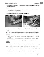
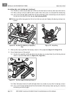
2. With the bed in a down position, working from under the rear of the vehicle, remove the two nylon lock-
nuts from the cargo bed hinge and bolts.
3. Apply slight upward pressure on the rear of the bed to relieve pressure from the hinges. Remove the
hinge bolts.
4. With the help from an additional person, or an overhead lift hoist, remove the bed from the vehicle.
CARGO BED INSTALLATION
NOTE:
Cargo bed removal and installation will be easier with the aid of an assistant.
1. With the help from an additional person, or an overhead lift hoist, place the bed onto the vehicle frame
and align the bed hinge brackets with the frame brackets.
2. Start the bolts into both hinges with the bolt heads to the outside. Use an alignment tool if necessary.
3. Use a small hammer, and lightly tap the bolts through the hinges.
4. Install a nylon locknut on each bolt, and tighten the hardware to 15 ft-lb (21 N·m).
5. Install the electric actuator.
See Bed Lift Motor Installation on page 4-9.
REAR FENDER
See General Warning, Section 1, Page 1-1.
REAR FENDER REMOVAL
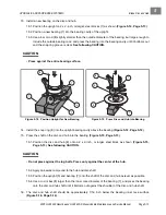
1. Remove the top Torx-head, self-tapping screw and washer.
2. Remove the three phillips-head side screws and washers from the rubber well nuts.
3. Remove the fender.
4. Repeat steps 1 through 3 to remove the remaining fender if necessary.
REAR FENDER INSTALLATION
1. Loosely install the three phillips-head side screws and washers into the rubber well nuts.
2. Install the top Torx-head, self-tapping screw and washer. Tighten the hardware to 50 in-lb (5.6 N·m).
3. Tighten the phillips-head side screws and washers to 13 in-oz (91.8 N·mm).
4. Repeat steps 1 through 3 to install the remaining fender if necessary.
Summary of Contents for HUV4420
Page 1: ... 5 5 2 4 56 56 3 3 6 3 4 3 26 5 ...
Page 2: ......
Page 16: ...Page xiv 2005 HUV4420 Gasoline and HUV4420 D Diesel Vehicle Maintenance and Service Manual ...
Page 20: ...1 ...
Page 38: ...4 ...
Page 68: ...5 ...
Page 74: ...6 ...


