BODY AND TRIM
Front Body Components
2005 HUV4420 Gasoline and HUV4420-D Diesel Vehicle Maintenance and Service Manual
Page 4-3
4
4.
Gasoline vehicles:
Remove the choke cable from the choke on the engine.
4.1. Remove the driver seat.
4.2. Loosen the two Tuflok screws from the rear of the console, and remove the screws and console.
4.3. Remove the component safety plate and engine handling eye bracket from the top of the engine.
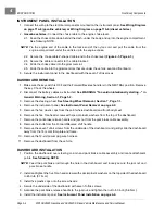
4.4. Remove the Z-shaped cable end (1) from the choke lever
(Figure 4-3, Page 4-3)
.
4.5. Remove the cable strain relief (2) from the cable bracket.
4.6. Remove the rubber grommet and cable from the engine plate (3).
4.7. Remove the cable from the two grommets under the frame.
See following NOTE.
NOTE:
Removing the rubber grommets from the cable will allow the cable to pass smoothly past wiring
and structural components.
Tie a nylon cord to the end of the cable before removal. Route the cord from the engine, under the
frame, and up to the instrument panel to be used during installation.
4.8. Feed the cable from the engine compartment, under the body, and up to the dash.
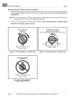
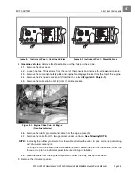
5. Remove the instrument panel.
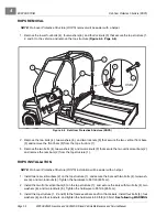
Figure 4-1 Instrument Panel – Gasoline Vehicles
Figure 4-2 Instrument Panel – Diesel Vehicles
Figure 4-3 Engine Choke Cable at Engine
(Gasoline Vehicles)
WARNING
!
WARNING
ON
OFF
START
0
1/2
1
1
10
WARNING
!
WARNING
PREHEAT
ON
OFF
START
0
1/2
1
1
10
3
2
1
Summary of Contents for HUV4420
Page 1: ... 5 5 2 4 56 56 3 3 6 3 4 3 26 5 ...
Page 2: ......
Page 16: ...Page xiv 2005 HUV4420 Gasoline and HUV4420 D Diesel Vehicle Maintenance and Service Manual ...
Page 20: ...1 ...
Page 38: ...4 ...
Page 68: ...5 ...
Page 74: ...6 ...


