BODY AND TRIM
Cargo Bed With Electric Lift
2005 HUV4420 Gasoline and HUV4420-D Diesel Vehicle Maintenance and Service Manual
Page 4-9
4
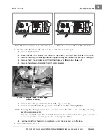
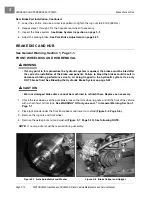
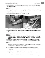
2. Install the coiled safety belt assembly on the outside of the ROPS seat frame with a new thread-forming
bolt. Orient the assembly with the tang end pointed up slightly, and tighten the hardware to 55 ft-lb
(75 N·m).
CARGO BED WITH ELECTRIC LIFT
See General Warning, Section 1, Page 1-1.
TESTING THE BED LIFT MOTOR
Gasoline Vehicles: See Test Procedure 29, Section 11a, Page 11a-38.
Diesel Vehicles: See Test Procedure 33, Section 11b, Page 11b-44.
BED LIFT MOTOR REMOVAL
1. Make sure the key switch is OFF and the Forward/Reverse handle is in the NEUTRAL position. Remove
the key. Chock the wheels.
2. Disconnect the battery cables as instructed.
See WARNING “To avoid unintentionally starting...” in
General Warning, Section 1, Page 1-2.
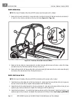
3. With the bed in the down position, working from under the vehicle, disconnect the two wires from the con-
nectors at the electric bed lift motor.
4. Remove the lock nut, bolt, sleeve, spacers and washers from the rod end of the bed lift motor and bed
frame.
5. Remove the lock nut, bolt, sleeve, spacers and washers from the base of the bed lift motor and vehicle
frame and remove the bed lift motor.
BED LIFT MOTOR INSTALLATION
NOTE:
If replacing the actuator, adjust the length of dimension between the base rod hole and the rod end
hole using the prior actuator as a guide. The rod end of the actuator can be turned clockwise to
shorten and counterclockwise to lengthen the dimension.
1. Make sure the key switch is OFF and the Forward/Reverse handle is in the NEUTRAL position. Remove
the key. Chock the wheels.
2. Disconnect the battery cables as instructed.
See WARNING “To avoid unintentionally starting...” in
General Warning, Section 1, Page 1-2.
3. With the bed in the down position, working from under the vehicle, mount the base of the bed lift motor
to the frame bracket.
3.1. Slide the metal sleeve into the bed lift motor base rod with two spacer washers on each side.
3.2. Slide a lock washer onto the bolt and up against the bolt head.
3.3. Fit the base between the frame bracket.
3.4. Slide the bolt through the frame bracket and actuator base.
3.5. Attach a lock washer and nylon lock nut finger tight.
NOTE:
Do not tighten the loser mounting hardware until the rod end has been secured.
4. Attach the rod end of the bed lift motor to the bed frame bracket.
Summary of Contents for HUV4420
Page 1: ... 5 5 2 4 56 56 3 3 6 3 4 3 26 5 ...
Page 2: ......
Page 16: ...Page xiv 2005 HUV4420 Gasoline and HUV4420 D Diesel Vehicle Maintenance and Service Manual ...
Page 20: ...1 ...
Page 38: ...4 ...
Page 68: ...5 ...
Page 74: ...6 ...

