HYDRAULIC AND PARK BRAKE SYSTEMS
Hydraulic Line Replacement
2005 HUV4420 Gasoline and HUV4420-D Diesel Vehicle Maintenance and Service Manual
Page 5-19
5
NOTE:
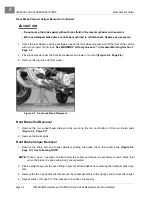
Place a plastic bag around the master cylinder to catch brake fluid before the brake line is
removed. Wrap the bag around the master cylinder to prevent debris from entering the brake line
port.
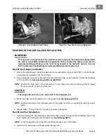
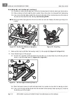
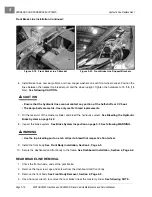
5. Remove the brake lines, banjo bolts and copper washers from each rear caliper assembly.
See follow-
ing NOTE.
NOTE:
Place a pan under each rear caliper assembly to collect the brake fluid.
Place a plastic bag around each caliper to prevent debris from entering the brake line ports. Do not
allow brake fluid to contact the brake pads and disc.
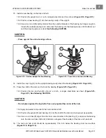
6. Remove each brake line from the grommet and clamp locations.
7. Remove the T-bracket from the passenger side on the rear receiver hitch frame.
8. Remove the brake line from the clamp locations under the vehicle frame and floorboard.
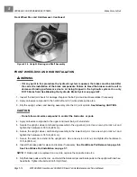
9. Remove the brake lines that are toward the rear of the vehicle on the passenger side.
See following
NOTE.
NOTE:
Tie a heavy nylon string to the flare-nut end of the brake line before removal. Allow the string to
travel with the brake line until it clears the rear of the vehicle. During replacement, tie the flare-nut
end of the new brake line to the nylon string, and use it to pull the new brake line into position and
to the master cylinder.
REAR BRAKE LINE INSTALLATION
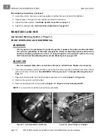
1. Feed a new brake line from the rear of the vehicle, and position it in line with the frame clamps and up
to the master cylinder.
See following NOTE.
NOTE:
If a heavy nylon string was used to remove the previous rear brake line, tie the string to the flare-
nut end of the new brake line. Use the string to pull the new brake line into position and to the mas-
ter cylinder.
2. Carefully install the flared end of the brake line into the master cylinder, and tighten to 11 in-lb (15 N·m).
3. Secure the brake lines to the clamp and grommet locations.
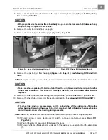
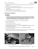
4. Secure the brake lines, banjo bolts, and new copper washers to each rear wheel caliper. Tighten the
hardware to 13 ft-lb (18 N·m).
See following NOTE.
NOTE:
Position the brake line perpendicular to the caliper assembly and pointing directly toward the base
bracket on the shock absorber.
See following CAUTION.
CAUTION
• The banjo bolts are metric. Use only metric thread replacements.
5. Fill the reservoir of the master cylinder, and bleed the hydraulic system.
See Bleeding the Hydraulic
Brake System on page 5-22.
6. Perform all of the brake system inspections.
See Brake System Inspection on page 5-1.
Summary of Contents for HUV4420
Page 1: ... 5 5 2 4 56 56 3 3 6 3 4 3 26 5 ...
Page 2: ......
Page 16: ...Page xiv 2005 HUV4420 Gasoline and HUV4420 D Diesel Vehicle Maintenance and Service Manual ...
Page 20: ...1 ...
Page 38: ...4 ...
Page 68: ...5 ...
Page 74: ...6 ...


