ACCELERATOR AND BRAKE PEDAL ASSEMBLIES
Brake Pedal
2005 HUV4420 Gasoline and HUV4420-D Diesel Vehicle Maintenance and Service Manual
Page 6-3
6
NOTE:
Use 1/4-turn adjustments, and check the RPM setting after each adjustment.
8. Adjust the screw until the RPM range is 3800 - 3850.
9. Connect the battery cables, positive (+) cable first, and tighten the hardware to 12 ft-lb (16 N·m). Coat
terminals with Battery Terminal Protector Spray (Husqvarna 603 00 00-03).
BRAKE PEDAL
See General Warning, Section 1, Page 1-1.
BRAKE PEDAL REMOVAL
1. Turn the key switch OFF, and place the Forward/Reverse handle in NEUTRAL. Remove the key, and
chock the rear wheels.
2. Disconnect the battery cables as instructed.
See WARNING “To avoid unintentionally starting...” in
General Warning, Section 1, Page 1-1.
3. Remove the dashboard.
See Dashboard Removal on page 4-4.
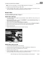
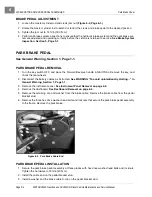
4. Remove the rue pin and the clevis pin. Separate the clevis from the brake pedal
(Figure 6-4, Page 6-3)
.
5. Remove the allen-head shoulder bolt and locknut from the pedal and frame brackets.
6. Remove the brake pedal.
7. Inspect the brake pedal bushing for wear and replace if necessary.
BRAKE PEDAL INSTALLATION
1. Position the brake pedal between the frame brackets.
2. Install the allen-head shoulder bolt and locknut. Tighten the hardware to 4.8 ft-lb (6.5 N·m).
3. Install the master cylinder rod and threaded clevis pin assembly.
4. Install the clevis pin and the rue pin.
5. Connect the battery cables, positive (+) cable first, and tighten the hardware to 12 ft-lb (16 N·m). Coat
terminals with Battery Terminal Protector Spray (Husqvarna 603 00 00-03).
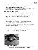
Figure 6-4 Clevis and Rue Pin
Summary of Contents for HUV4420
Page 1: ... 5 5 2 4 56 56 3 3 6 3 4 3 26 5 ...
Page 2: ......
Page 16: ...Page xiv 2005 HUV4420 Gasoline and HUV4420 D Diesel Vehicle Maintenance and Service Manual ...
Page 20: ...1 ...
Page 38: ...4 ...
Page 68: ...5 ...
Page 74: ...6 ...

