HYDRAULIC AND PARK BRAKE SYSTEMS
Master Cylinder and Reservoir
Page 5-20
2005 HUV4420 Gasoline and HUV4420-D Diesel Vehicle Maintenance and Service Manual
5
MASTER CYLINDER AND RESERVOIR
See General Warning, Section 1, Page 1-1.
ý
WARNING
• To perform this procedure, the hydraulic system must be opened. As a result, the brakes must
be bled after the correct reinstallation of the brake components. Failure to bleed the brakes
could result in decreased braking performance due to air being trapped in the hydraulic
system. Use only DOT 5 brake fluid. See Bleeding the Hydraulic Brake System on page 5-22.
FILLING THE HYDRAULIC SYSTEM
The brake fluid reservoir is accessible through the door on top of the dashboard. Do not allow the brake fluid
level to fall below the MIN line. Use only DOT 5 brake fluid.
RESERVOIR REMOVAL
1. Chock the wheels, and set the park brake.
2. Remove the instrument panel.
See Instrument Panel Removal, Section 4, Page 4-2.
3. Remove dashboard.
See Dashboard Removal, Section 4, Page 4-4.
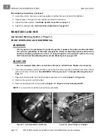
4. Remove front body.
See Front Body Removal, Section 4, Page 4-5.
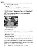
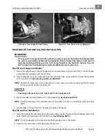
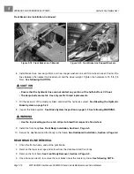
5. Remove the hoses at the master cylinder.
See following NOTE.
NOTE:
Provide a clean container for the brake fluid to drain into. After both hose ends are in a container,
remove the reservoir cap to allow fluid to drain freely from reservoir container.
6. Remove the hoses at the reservoir.
NOTE:
If hoses are cracked or show signs of aged deterioration, replace them with approved hoses
designed to handle brake fluid specified for this vehicle.
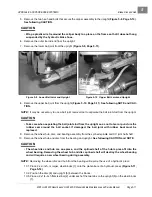
7. Remove the bolt, washer and lock nut that secure the reservoir container to the steering column frame
plate, and remove the container.
RESERVOIR INSTALLATION
1. Secure the reservoir container to the steering column frame plate with a bolt, washer and lock nut and
tighten the hardware to 20 in-lb (2.2 N·m).
2. Install the hoses on the barbed fittings of the reservoir container.
3. Install the remaining loose hose ends on the barbed ports of the master cylinder.
See following NOTE.
NOTE:
The front port on the reservoir should be attached to the corresponding front port on the master cyl-
inder.
Do not allow these hoses to develop kinks or be routed in such a way as to restrict gravity fluid flow.
4. Fill the reservoir with brake fluid specified for this vehicle, and bleed the hydraulic brake system.
See
Bleeding the Hydraulic Brake System on page 5-22.
5. Inspect the brake system.
See Brake System Inspection on page 5-1.
Summary of Contents for HUV4420
Page 1: ... 5 5 2 4 56 56 3 3 6 3 4 3 26 5 ...
Page 2: ......
Page 16: ...Page xiv 2005 HUV4420 Gasoline and HUV4420 D Diesel Vehicle Maintenance and Service Manual ...
Page 20: ...1 ...
Page 38: ...4 ...
Page 68: ...5 ...
Page 74: ...6 ...

