background image

EQUIPMENT INFORMATION 65

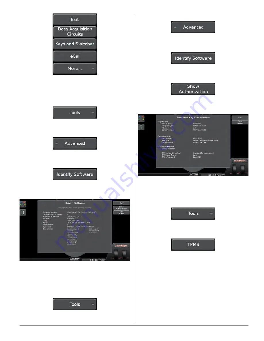
Touch the “Advanced” button. 

Figure 280. 

Touch the “Identify Software” button. 

Figure 281. 

Touch the “Show Authorization” button.

Figure 282. 

The Electronic Key Authorization screen is displayed. 

Figure 283. 

TPMS

From the main balance screen, touch the “Tools” button. 

Figure 284. 

Touch the “TPMS” button. 

Figure 285. 

Figure 274. 

Identify Software

From the main balance screen, touch the “Tools” button. 

Figure 275. 

Touch the “Advanced” button. 

Figure 276. 

Touch the “Identify Software” button.

Figure 277. 

The Identify Software screen is displayed. 

Figure 278. 

Authorization

From the main balance screen, touch the “Tools” button. 

(Figure 279.)

Figure 279. 

Summary of Contents for GSP9200 Touch

Page 1: ...Copyright 2012 2014 Hunter Engineering Company Form 6555TE 05 05 14a Supersedes Form 6555TE 05 09 12 SmartWeight Touch and GSP9200 Touch Wheel Balancer Operation Instructions Software Version 2 0 ...

Page 2: ......

Page 3: ...ing a Spin 9 Main Balance Screen Servoing To Position 10 Main Balance Screen SmartWeight Buttons 10 2 Introduction to Balancing 11 2 1 Balance Forces 11 Balancing Theory Static Imbalance 11 Balancing Theory Couple Imbalance 12 2 2 SmartWeight Balancing Technology 13 Static and Dynamic Imbalance Sensitivity 13 2 3 SmartWeight Balancing Technology Dynamic Weight Planes 14 2 4 Using SmartWeight Balan...

Page 4: ...pecific Weight Types and Placement using TruWeight 35 Dimensions Entry 35 Dimensions Entry Inner Clip 35 Dimensions Entry Inner Tape 35 Dimensions Entry Outer Tape 36 Dimensions Entry Enter Spoke s 36 Dimensions Entry Outer Clip 36 Dimensions Entry Inner and Outer Clip 36 Balancing Procedure Using Clip On Weights 36 Balancing Procedure Using a Combination of Clip On Adhesive Tape Weights Mixed Wei...

Page 5: ...res 64 Diagnostics 64 Identify Software 65 Authorization 65 TPMS 65 Clean Threads 67 Balance Bare Rim 67 4 2 USB Program Flash Drive and Security Key Removal and Installation 68 5 Calibration and Maintenance 69 5 1 Calibration Procedures 69 eCal Auto Calibration 69 Calibration Procedures 69 Calibration Check 70 5 2 Diagnostic Tools 71 Data Acquisition Circuits 71 Keys and Switches 71 eCal 71 Spind...

Page 6: ...THIS PAGE INTENTIONALLY LEFT BLANK iv ...

Page 7: ...s Quick Thread AutoClamp optional Autostart Servo Stop Maintenance Calibration Cleaning Lubrication and Maintenance of Adaptors Hub and Shaft Calibrating the Balancer Calibrating the Load Roller and Dataset Arms Calibrating the Inflation Station Mounting the Wheel Tire Assembly Verifying Mounting Repeatability with Centering Check Feature Cone Mounting Pressure Ring and Spacers Flange Plate and Co...

Page 8: ..._____________________ ___________________________________ _____________________________________ ___________________________________ _____________________________________ ___________________________________ _____________________________________ ___________________________________ _____________________________________ ___________________________________ _____________________________________ ________...

Page 9: ...ords of personnel trained is solely the responsibility of the owner and management This manual assumes the technician has already been trained in basic balancing procedures References This manual assumes that you are already familiar with the basics of tire balancing The first section provides the basic information needed to operate the SmartWeight Touch GSP9200 Touch The following sections contai...

Page 10: ...e stop If safety hood is raised before the spin is completed the weight values will not be displayed Do not let cord hang over any edge or contact fan blades or hot manifolds 1 2 For Your Safety Hazard Definitions Watch for these symbols CAUTION Hazards or unsafe practices which could result in minor personal injury or product or property damage WARNING Hazards or unsafe practices which could resu...

Page 11: ...ith proper grounding To prevent the possibility of electrical shock injury or damage to the equipment when servicing the balancer power must be disconnected by removing the power cord from the electrical power outlet After servicing be sure the balancer ON OFF switch is in the O off position before plugging the power cord into the electrical power outlet This device is rated as Class A for radiate...

Page 12: ... L ISTED 309121 2 128 1120 2 128 381 2 128 1120 2 Figure 3 Specific Precautions Power Source The SmartWeight Touch GSP9200 Touch Balancer is intended to operate from a power source that will apply 230VAC 10 15 1 phase 10 amp 50 60 Hz power cable includes NEMA 20 amp plug L6 20P between the supply conductors of the power cord The power cord supplied utilizes a twist lock connector NEMA L6 20P Figur...

Page 13: ...d condition For information on converting from single phase NEMA L6 20P plug to thee phase NEMA L15 20P plug refer to Form 5350 T NEMA L6 20P to NEMA L15 20P Power Plug Conversion Instructions Specific Precautions BDC Laser Indicator The BDC Bottom Dead Center Laser Indicator is a class 1M laser designed to aid in applying adhesive weights The laser is not a field serviceable or adjustable part Us...

Page 14: ... Service Representative Equipment Specifications Electrical Voltage 230VAC 10 15 1 phase 50 60 Hz power cable includes NEMA 20 amp plug L6 20P Amperage 10 amperes Wattage 3450 watts peak Air Air Pressure Requirements 100 175 PSI 6 9 12 0 bar Approximate Air Consumption 4 CFM 110 Liters Minute Atmospherics Temperature 0 C to 50 C 32 F to 122 F Relative Humidity Up to 95 Non condensing Altitude Up t...

Page 15: ... 3 SmartWeight Touch GSP9200 Touch Components SAFETY HOOD OUTER DATASET ARM SPINDLE SHAFT INNER DATASET ARM FOOT PEDAL INFLATION STATION BULLSEYE CENTERING SYSTEM COLLET STORAGE WEIGHT TRAY TOUCH SCREEN DISPLA Y Figure 10 ...

Page 16: ...ure 11 1 Tire Stack Vehicle Plan View Tab 6 Wheel Assembly Display 2 Wheel Dimensions Tab 7 Start Stop Button 3 Clip Weight Plane 8 SmartWeight Menu Button 4 Tape Weight Plane 9 Imbalance and Couple Force Display 5 Context Sensitive Menu 10 SmartWeight Savings Total 10 ...

Page 17: ...opriate information will be displayed For example the above screen is displayed if operator attempts to start a spin without first lowering the hood Figure 13 Main Balance Screen Prompt Text When the operator needs more info in a non error condition prompting text will appear in the lower portion of the screen Figure 14 Main Balance Screen Performing a Spin During a balance spin several things occ...

Page 18: ...p dead center To servo to the next position the operator can either touch the Start button or touch the corresponding weight amount Figure 17 Main Balance Screen SmartWeight Buttons Touching the SmartWeight button expands a set of button options SmartWeight can be disabled or enabled Performance Mode can be disabled or enabled and Weight savings can be viewed Figure 18 ...

Page 19: ...Figure 19 CUPPING Figure 20 Static imbalance is a condition where one amount of weight located in the center of the tire wheel assembly causing an imbalance As the weight rotates centrifugal forces are created causing the wheel to lift as the weight reaches top dead center This lifting motion causes the tire wheel assembly to move up and down creating a bounce that can be felt This static imbalanc...

Page 20: ...ded procedure For example a single weight is commonly placed on the inner clip weight position for cosmetic purposes This is not a recommended practice and usually insures the assembly is not properly dynamically balanced The assembly may then experience side to side imbalance while in motion causing a shimmy condition and objectionable vibration BALANCE WEIGHT IS NOT IN CENTER OF WHEEL NON RECOMM...

Page 21: ...tic imbalance should be less than 1 4 ounce 7 grams Residual couple imbalance should be less than 3 4 ounce 21 grams Residual couple imbalance is preferred over remaining static imbalance It takes much more residual couple imbalance weight to cause a vibration than the same amount of static imbalance correction weight The larger the diameter used for weight placement the smaller the amount of corr...

Page 22: ...es that are above that level will be shown in red and indicate an excessive amount of force Install a tire wheel assembly as normal Rim measurements are not required to determine if the balance forces are exceeded Lower the hood and spin Figure 29 2 3 SmartWeight Balancing Technology Dynamic Weight Planes SmartWeight requires the operator to enter at least two weight planes This balancing method w...

Page 23: ...that both standard and SmartWeight balancing modes are enabled in setup Touch the SmartWeight button to display the SmartWeight menu buttons Figure 35 Figure 35 Prior to balance spin the tire graphs will display no color The SmartWeight balance force graphs will display red for excessive forces and green for acceptable amounts of force Figure 30 If the SmartWeight balancing procedure requires corr...

Page 24: ...tWeight mode the balancer can be switched to performance mode Touch the Enable Performance Mode button SmartWeight Balancing Technology is the default balancing method and is the most recommended way to accurately balance wheel tire assemblies Touch the Disable SmartWeight button Figure 36 The balancer is now in traditional dynamic balancing mode Figure 37 When changing to traditional dynamic bala...

Page 25: ... 45 The SmartWeight Savings screen will be displayed Figure 46 Touch the Show Details button to view details of SmartWeight savings Figure 47 The Weight Savings screen will be displayed Figure 48 Touch the Investment Return button Figure 49 The SmartWeight Investment Return screen will be displayed ...

Page 26: ...THIS PAGE INTENTIONALLY LEFT BLANK 18 INTRODUCTION TO BALANCING ...

Page 27: ...GSP9200 Touch GSP9200 Touch series balancer Raising the Wheel Assembly Slide the appropriate Bullseye Centering System collet onto the spindle shaft Position wheel lift carriage at the end of the wheel lift rail COLLET WHEEL LIFT CARRIAGE WHEEL LIFT RAIL Figure 51 Press the lift control handle down until the trolley carriage is at its lowest level Figure 52 ...

Page 28: ...embly raise the lift control handle up to move the lifting assembly to the wheel assembly Figure 58 Roll the wheel assembly onto the wheel lift carriage Figure 53 Raise the lift control handle up to move the lifting assembly into a position where the wheel assembly can be installed onto the spindle shaft Figure 54 Slide the tire wheel assembly onto the spindle and center on the collet Verify that ...

Page 29: ... Inspect inside of wheel for excessive accumulation of dirt and debris Remove if necessary before balancing Accurate balancing depends on accurately centering the wheel Choose the proper Bullseye Centering System collet by placing it in the center hole of the wheel to be balanced If basic collets and adaptors do not fit the wheel additional centering adaptors will be necessary A wheel that cannot ...

Page 30: ... the spindle shaft against the captivated spring SPINDLE SHAFT COLLET CAPTIVATED SPRING Figure 65 Position the wheel with the inside surface facing the balancer centered on the collet TIRE WHEEL ASSEMBLY CENTERED ON COLLET Figure 61 Install the plastic clamping cup and wing nut on the spindle shaft against the wheel and secure the entire assembly by firmly tightening the wing nut PLASTIC CLAMPING ...

Page 31: ...lowed is minimal Therefore the wing nut must still be hand tightened before balancing Installing the Wheel Using Auto Clamp Wheel Clamping Optional With the safety hood open place the collet on the spindle shaft against the captivated spring Position the wheel with the inside surface facing the balancer centered on the collet TIRE WHEEL ASSEMBLY CENTERED ON COLLET Figure 69 Lift the wheel assembly...

Page 32: ...Install the plastic clamping cup and Auto Clamp device by sliding onto the spindle shaft with the clamping cup pressed against the wheel PLASTIC CLAMPING CUP AUTO CLAMP DEVICE Figure 70 Rotate the Auto Clamp device until it locks into place on the spindle shaft ROTATE UNTIL LOCK Figure 71 Keep hands clear of clamping components during Auto Clamp operation Secure the wheel by tapping the Spindle Lo...

Page 33: ...y possible centering errors thus recognizing improper measurements From the main balance screen touch the CenteringCheck button Figure 74 CenteringCheck Errors If an error condition occurs during the procedure an error popup will appear with text explaining the error Follow the on screen instructions to correct the error and proceed with CenteringCheck Balance Mode CenteringCheck Balance Mode Cent...

Page 34: ...ounting Error Detection Features To verify that the tire wheel assembly is centering re mount the tire wheel assembly and observe the results Do any of the following conditions occur Weight amount varies excessively Weight location changes If any of these conditions occur the centering accuracy of the tire wheel assembly needs to be verified Spindle Lok foot pedal to enter the valve stem position ...

Page 35: ...ure The scratch guard may be installed on the clamping cup to protect alloy rims from being marred but should not be used on steel wheels 3 4 Front Back Collet Mounting Collet mounting is one of the most common and reliable ways to mount wheels on balancers The Bullseye Centering System is a set of collets that provides wheel centering coverage for most passenger cars and light trucks Due to the d...

Page 36: ...NDLE SHAFT CERTAIN LIGHT TRUCK RIMS COLLET WING NUT Figure 92 Heavy Wheel Centering Heavy wheel centering may benefit by 1 pulling the tire away from the hub face at top dead center while tightening the wing nut or 2 use of optional wheel lift to position heavy wheel onto shaft and cone This helps the wheel to overcome gravity against the hub or spacer LARGE OFFSET RIM SPINDLE SHAFT SCRATCH GUARD ...

Page 37: ... WHEEL AND LIGHT TRUCK SPACER Figure 95 3 5 Specialized Mounting Conditions Collet Flange Plate Mounting Some wheels may be centered using the lugholes and center bore with a flange plate and collet It is important that a back mounted collet be used to support and center the wheel when using flange plates CAPTIVATED SPRING PLATE SPINDLE SHAFT COLLET WING NUT ADJUSTABLE FLANGE PLATE PRESSURE RING F...

Page 38: ... ensuring the lug nuts bolts are tightened equally while rotating the wheel Figure 98 1 3 2 4 1 3 2 4 5 1 3 2 4 5 6 Figure 98 3 6 On Vehicle Wheel Installation Methods Hub Centric A hub centric wheel is aligned to the hub by the center bore of the wheel The vehicle weight rests on the hub bore The clearance between the hub bore and the hub on a hub centric wheel is between 0 003 and 0 004 of an in...

Page 39: ...h GSP9200 Touch automatically tracks the wheel assembly currently being balanced The balancer assumes that the technician is working around the vehicle by beginning at the LEFT FRONT and working around the vehicle in a clockwise fashion Successive spins are stored as either before or after data based on the following rules If the weight displays read OK OK or is blank assume the next complete spin...

Page 40: ...o create custom printouts Information such as the shop name customer name vehicle etc can be displayed on the printout Figure 105 Information for the printout can be entered using the on screen keyboard Figure 106 Also custom data such as before service after service individual tire pull etc can be toggled on or off for the printout Figure 107 Once the options are set for the printout they can be ...

Page 41: ...cing time required check spins needed and weight chasing SmartWeight saves the shop time and money Figure 112 Dynamic Balancing Traditional Balancing Mode SmartWeight Balancing Technology is the default balancing method and is the most recommended way to accurately balance wheel tire assemblies Enter wheel dimensions before selecting dynamic balancing If SmartWeight mode is enabled in setup the ba...

Page 42: ...ncing Dynamic balancing should be selected whenever possible to minimize vehicle vibration Switching from Traditional Dynamic Balancing to Traditional Static Balancing In non SmartWeight mode the balancer can be switched from dynamic balancing to static balancing Dynamic mode is selected Figure 118 Touching the static mode icon will switch to static mode Figure 119 Blinding and Rounding In non Sma...

Page 43: ...ght modes are available for both dynamic and static balancing With these options correction weights can be placed at an infinite number of locations based upon the choice of the operator Automatic is the default setting automatically choosing the correct type of weights and locations determined by the placement of the Dataset arms TruWeight shows the operator exactly how to place the weights on th...

Page 44: ...gure 131 Balancing Procedure Using Clip On Weights Figure 132 Dimensions Entry Outer Tape Pulling out only the inner Dataset arm pointing it down and pressing on the foot pedal records the first dimension Since the Dataset arm is still in the down position this signals to the balancer that the operator wants to measure the second inner plane tape dimension Figure 128 Dimensions Entry Enter Spoke s...

Page 45: ...sition while the weight is applied Figure 137 Attach the weight amount shown on the screen for the selected weight plane to the correct side of the wheel TruWeight shows the operator exactly how to place the weights on the wheel Place them exactly as displayed on the screen If the optional HammerHead TDC weight locator is installed the weight should be applied at the location marked by the laser C...

Page 46: ...e 139 The SmartWeight Touch GSP9200 Touch will rotate the wheel to TDC for the next weight plane The view of the wheel will also change to the next plane view and the weight amount for the next plane will be displayed in green Figure 140 Optionally pressing the next plane weight amount will rotate the wheel to TDC for the next weight plane Attach the weight amount shown on the screen for the selec...

Page 47: ...an be toggled to display either ounces or grams by pressing the oz or g graphic shown after the weight amount Figure 150 After wheel comes to a complete stop raise safety hood If Auto Hood is enabled the hood will raise automatically Verify that the wheel is clean and free of debris Remove all previous weights Mount tire wheel assembly Use the inner Dataset arm in the UPWARD position at the clip o...

Page 48: ...ty hood to perform a check spin Left and right weight plane displays should show OK after check spin Figure 155 MIXED WEIGHTS balancing procedure is complete The SmartWeight Touch GSP9200 Touch will find the top dead center TDC for the first weight plane if Servo Stop is enabled Servo Stop will hold the wheel in the TDC position while the weight is applied Figure 151 Attach the clip on weight amou...

Page 49: ... pedal Figure 160 INNER DATASET ARM Figure 161 Balancing Procedure Using Adhesive Tape Weights Figure 156 LEFT DIAMETER RIGHT PLANE LEFT PLANE RIGHT DIAMETER TAPE WEIGHT TAPE WEIGHT Figure 157 Verify that the wheel is clean and free of debris Remove all previous weights Mount tire wheel assembly Using the DOWNWARD position move the inner Dataset arm disk edge to the location for placement of the l...

Page 50: ... 165 Optionally pressing the next plane weight amount will rotate the wheel to the next weight plane Close the safety hood to perform a check spin Left and right weight plane displays should show OK after the check spin If the Split Spoke feature of hiding weights behind spokes is to be used position the Dataset arm disk in the center of a spoke and tap the foot pedal Figure 162 Move to the next s...

Page 51: ...tion measurements for balancing Automatic Weight Position Measurement The Dataset arms can be used to enter weight position dimensions instantly and accurately The arms are triggered when they are moved away from their home position When the arms are triggered graphic representation on the screen identifies the plane currently being inputted Figure 167 Figure 168 In most cases the Dataset Arms are...

Page 52: ...ounding are disabled as shown below Dynamic mode blinding rounding is disabled Figure 172 Static mode blinding rounding is enabled Figure 173 Manual Weight Position Measurement Touch the screen in the upper rim profile area to toggle manual weight selection The balancer will switch to Manual Weight Selection mode Figure 169 Touching the weight locations will change the weight location planes Figur...

Page 53: ...hts Figure 177 If the servo is on at the time of the split the wheel will move one of the split weights to BDC and turn on the laser for weight placement Repeated touches of Split the Weight will provide alternate choices where the weights fan further apart but become larger to accommodate the correction needed 3 12 Tape Weight Menu By touching a weight on the wheel such as the strips of weight sh...

Page 54: ... as normal To return to the single weight touch Split the Weight repeatedly until the weights become larger than the single weight and return to the un split weight Figure 178 Correcting Large Imbalances Split Weight can also be used to apply three weights when needed For example a large wheel may require 6 75 ounces Not only is this size unlikely to be in the weight tray but splitting 6 75 ounces...

Page 55: ...on fields Wavelength 635 660nm Laser Power for Classification 1mW via 7mm aperture Beam Diameter 5mm at aperture Divergence 1 5mrad x 2rad Transverse Beam Mode TEM00 3 14 BDC Laser Adhesive Weight Locator The Servo Activated Laser automatically locates BDC to aid in fast adhesive weight positioning During the mixed weights and adhesive weights balancing procedures the BDC laser locator automatical...

Page 56: ...red on Tire Rotation or Replacement Reset Tool Requirement Required Tools Reset Procedure TPMS Hints Information Disclaimers TPMSpecs may be accessed in two ways Option 1 From the Main Balance screen scan a VIN barcode TPMS information for the vehicle scanned will be automatically retrieved and displayed Option 2 From the main balance screen touch the Tools button Figure 183 Touch the TPMS button ...

Page 57: ...quired optional or not required Red and white striped border indicates the requirement is possibly required refer to the explanation below the images Figure 188 Scroll up or down by dragging the scroll bar or touching the up and down arrows on the right side of the screen Figure 189 Touch the Home button to return to the main TPMSpecs Menu Figure 190 Touch the arrows to navigate backward or forwar...

Page 58: ...00 To access the Video Player From the main balance screen touch the Help button Figure 194 Touch the Launch Video Player button Figure 195 The main video menu screen is displayed Figure 196 Select a topic from the menu to view the video Figure 197 Touch the print button to print the current page Figure 192 Touch X to return to the balancer screen Figure 193 ...

Page 59: ... as it becomes available To access Hunter Help From the main balance screen touch the Help button Figure 206 Touch the Launch Help button Figure 207 The video screens may change as new content is added The selected video will begin playing Go back in the video by touching the back button Figure 198 Play the video by touching the play button Figure 199 Stop the video by touching the stop button Fig...

Page 60: ...e print button to print the current page Figure 214 Touch X to return to the balancer screen Figure 215 The Main Menu of Hunter Help is displayed Select the item to view by touching the selection Figure 208 The help screens may change as new content is added Some items have sub menus that will display help on a specific topic Touch to view the selected topic Figure 209 Detailed help on specific to...

Page 61: ...e items to include in the printout When a custom summary is created it can be saved by touching the Save This Option Set button Figure 218 Custom vehicle summaries can be recalled by touching the Recall Next Option Set button Figure 219 Print information can also be entered in the text boxes on the Vehicle Summary screen Use Header to display shop name address and phone or any custom message to ap...

Page 62: ...rotate one full turn onto the spindle threads With the right hand hold one handle of the wing nut while lifting the rim Heavier wheel assemblies may require extra lifting to prevent the software limited motor torque control from stopping the rotation of the spindle Tap the foot pedal twice and the spindle will rotate to install the wing nut to save threading time The direction of spindle rotation ...

Page 63: ...ion of the spindle When the Start button is touched with the hood in the raised position while weights are showing the motor will automatically rotate the wheel to the next weight plane and hold the assembly in position for weight or mark application Alternatively touching the weight amounts will achieve the same results Figure 222 Spindle Lok Feature Depressing the foot pedal will lock the spindl...

Page 64: ...hen the SmartWeightTouch senses that the wheel is loose it will automatically stop the spin Secure the tire wheel assembly before proceeding If the wing nut appears to be tight remove the wing nut and then clean and lubricate the spindle threads Figure 223 ...

Page 65: ...perator to check balancer calibration From the main balance screen touch the Tools button Figure 224 Touch the Quick Calibration Check button Figure 225 Install the calibration weight on the spindle faceplate and follow the on screen instructions Figure 226 After calibration check remove calibration weight Set Up The Set Up screen contains a list box of balancer set up items Figure 227 ...

Page 66: ...ored until Store Set Up is touched Figure 237 To abandon the set up procedures without saving changes touch the Exit button or reset the system Figure 238 Reset All Button Clears all data and returns the balancer to a freshly booted condition From the main balance screen touch the Tools button Figure 228 Touch the Advanced button Figure 229 Touch the Set Up button Figure 230 Change set up features...

Page 67: ...eep and click sounds Video volume is adjustable on the selected video screen Figure 239 Specification Database The specification database can be accessed by two different methods Touch the specification database tab button or touch the text that says No Vehicle Selected Figure 240 A drop down list appears listing vehicle makes Touch the desired make year and model Figure 241 Navigation buttons at ...

Page 68: ...the Advanced button Figure 250 Touch the Set Up button Figure 245 Date and Time Date and time can be set by user There is also support for international date format DD MM YYYY From the set up screen touch Set Date and Time Touch the desired time zone Figure 246 Touch the desired date and time Touch the box next to the desired date format Figure 247 To set up a desired time zone touch Edit Time Zon...

Page 69: ...elects the language for on screen display Print Language Selects the language for printouts Printer Sets printer output to the desired printer Print Preview Enables or disables print preview Figure 251 The screen will display a list of available set up options Scroll down and touch 3M Tape Weights Touch the Set Up and Selected Item button Figure 252 Touch the boxes that match the size and shape pr...

Page 70: ...el Dimensions button Touch the Manual Entry button Figure 259 In this example no dimensions have been entered Printout Paper Size Selection Selects the size of paper for printouts Selectable Print Destination From any printable screen or report there is now an option to print to multiple destinations For example if there is a printer attached to the balancer and a thumb drive is plugged into a USB...

Page 71: ...oad roller will automatically disabled as necessary Options are Disabled or Enabled Weight Units Use Weight Units to select ounces or grams for displaying wheel weights Background Color Changes the background color of all screens Use a tape measure to obtain the outer rim dimension Touch the box and use the keypad to enter the dimension Rpeat for the rim width dimension Figure 260 Touch the inner ...

Page 72: ...ibration Procedures Using calibration procedures the operator can calibrate the following systems Inner Dataset Outer Dataset The operator can also perform a 3 Spin Balancer Calibration and check calibration of any of the systems From the main balance screen touch the Tools button Figure 265 Touch the Advanced button Figure 266 Touch the Calibration Procedures button Figure 267 The main Calibratio...

Page 73: ...3 TPMS From the main balance screen touch the Tools button Figure 284 Touch the TPMS button Figure 285 Figure 274 Identify Software From the main balance screen touch the Tools button Figure 275 Touch the Advanced button Figure 276 Touch the Identify Software button Figure 277 The Identify Software screen is displayed Figure 278 Authorization From the main balance screen touch the Tools button Fig...

Page 74: ...or not required Red and white striped border indicates the requirement is possibly required refer to the explanation below the images Figure 289 Scroll up or down by dragging the scroll bar or touching the up and down arrows on the right side of the screen Figure 290 Figure 290 Touch the Home button to return to the main TPMSpecs Menu Figure 291 Figure 291 Touch the arrows to navigate backward or ...

Page 75: ...king dimensions applying weights etc Touch the print button to print the current page Figure 293 Touch X to return to the balancer screen Figure 294 Clean Threads From the main balance screen touch the Tools button Figure 295 Touch the Clean Threads button Figure 296 The main Clean Threads Explanation screen is displayed Figure 297 Follow the on screen instructions to clean the spindle threads Aft...

Page 76: ...B sockets on the Mini ITX Atom Motherboard Verify that the USB drives are fully seated Figure 304 Install the supplied electronic security x key s in the button socket on the board within the support assembly Figure 305 Taking care not to pinch any cables re install the rear cover to the support assembly with the previously removed screws The balancer must be completely re calibrated after program...

Page 77: ...equired Calibration Procedures Using calibration procedures the operator can calibrate the following systems Inner Dataset Outer Dataset Load Roller The operator can also perform a 3 Spin Balancer Calibration and check calibration of any of the systems From the main balance screen touch the Tools button Figure 306 Touch the Advanced button Figure 307 Touch the Calibration Procedures button Figure ...

Page 78: ...e balancer using a calibration weight From the main balance screen touch the Tools button Figure 311 Touch the Quick Calibration Check button Figure 312 Screw in the calibration weight and clamp a large cone or collet to the shaft Lower the hood and press start to begin the check Figure 313 Rotate the shaft to the 12 00 position until the yellow dot on the screen turns green to complete the check ...

Page 79: ...ols From the main balance screen touch the Tools button Figure 315 Touch the Advanced button Figure 316 Touch the Diagnostics button Figure 317 The main Diagnostics screen is displayed Figure 318 Most of the diagnostic data is for the sole purpose of conveying information to the Hunter Service Representative The service representative may request information from these screens to diagnose service ...

Page 80: ...Dataset Arm Sensors button Figure 331 The Dataset Arm Sensors screen is displayed Figure 332 The eCal screen is displayed Figure 324 Touch the eCal History button Figure 325 Choose which eCal history timeframe to view The eCal history is displayed Figure 326 Spindle Encoder Touch the More button Figure 327 Touch the Spindle Encoder button Figure 328 ...

Page 81: ... cabinet Do not spray window cleaning solution directly onto LCD Power should be OFF prior to cleaning the LCD Exposing the balancer to water either by hose bucket or weather may cause risk of electrical shock to operator or bystanders and will damage the electrical system Place store and operate the balancer only in a dry sheltered location Cleaning the Screen Do not touch the screen with chemica...

Page 82: ...specified herein may result in hazardous radiation exposure This Laser Product is designated as Class 2M during all procedures of operation Do not stare into the beam or view directly with optical instruments Doing so may cause serious injury Do not intentionally use a reflective device to enhance or re direct the laser Do not operate the laser if the cover or seal is damaged There is no required ...

Page 83: ...ng sets the weight increments to specific amounts such as tenths or quarters etc Bolt Pattern Circle The diameter of an imaginary circle drawn through the center of each lughole and virtually always on the same centerline as the hub bore of the wheel CenteringCheck Hunter feature that ensures the wheel is properly centered when mounted on the balancer Couple Balance A procedure that corrects the i...

Page 84: ...tion where the tire and wheel assembly is slightly out of round forcing the spindle to move up and down as the vehicle rolls along a smooth surface Harmonic A vibration that is identified by the number of occurrences per revolution For example a 1st harmonic vibration has a once per revolution vibration component Hertz A unit of frequency one disturbance per second Hub Centric The wheel is centere...

Page 85: ...uency matches the natural frequency of another component Responding Component The noticeable component that is vibrating Road Force A change in the force between the wheel and the axle while rotating under a load Discrepancy in road force can cause a vibration although the tire and rim may be perfectly round and the tire is balanced Road Force Measurement A measurement of the wheel assembly as wou...

Page 86: ...n measured on the inside of the rim at the bead seats Wheel Offset The measured distance between the mounting face of the wheel and the centerline of the rim Wheel Width Dimension measured on the inside of the rim between the bead seats ...

Page 87: ...THIS PAGE INTENTIONALLY LEFT BLANK ...

Page 88: ...www Hunter com ...

Reviews: