BALANCING PROCEDURES 37
Close safety hood.
Touch the green “START” button if “Hood Autostart” is
disabled.
As the wheel is spinning, the amount(s) of corrective
weight(s) needed will be shown on the screen. This time
can be used to find and prepare the needed weights.
Once weight amounts are shown on the screen,
they can be toggled to display either ounces or
grams by pressing the “oz” or “g” graphic shown
after the weight amount.
Figure 136.
After wheel comes to a complete stop, raise the safety
hood.
If Auto Hood is enabled, the hood will raise
automatically.
The SmartWeight Touch®/GSP9200 Touch will find the
top-dead-center (TDC) for the first weight plane if “Servo-
Stop” is enabled. “Servo-Stop” will hold the wheel in the
TDC position while the weight is applied.
Figure 137.
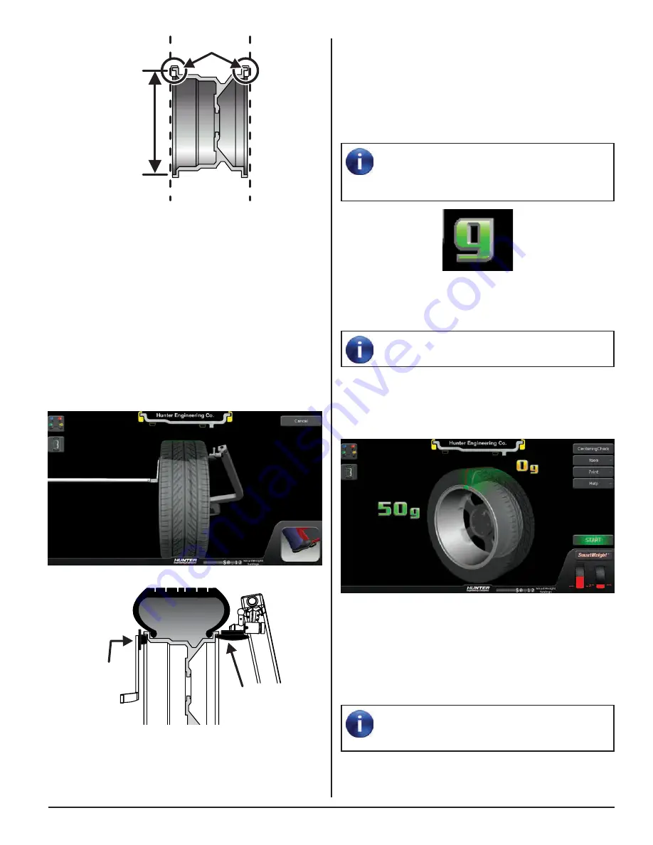
Attach the weight amount shown on the screen for the
selected weight plane to the correct side of the wheel.
TruWeight™ shows the operator exactly how to place the
weights on the wheel. Place them exactly as displayed on
the screen.
If the optional HammerHead
®
TDC weight
locator is installed, the weight should be applied
at the location marked by the laser.
CLIP-ON
WEIGHT
DIAMETER
RIGHT
PLANE
LEFT
PLANE
Figure 133.
Verify the correct clip-on weight type will be used for the
wheel that is being balanced.
Verify that the wheel is clean and free of debris.
Remove all previous weights.
Mount tire/wheel assembly.
Use both Dataset® arms in the UPWARD position at the
clip-on weight location to measure the distance, diameter,
and rim width dimensions.
Figure 134.
INNER
DATASET
ARM
OUTER
DATASET
ARM
Figure 135.
Enter the rim data by depressing the foot pedal. Release
the Dataset® arms.
Summary of Contents for GSP9200 Touch
Page 2: ......
Page 6: ...THIS PAGE INTENTIONALLY LEFT BLANK iv ...
Page 26: ...THIS PAGE INTENTIONALLY LEFT BLANK 18 INTRODUCTION TO BALANCING ...
Page 87: ...THIS PAGE INTENTIONALLY LEFT BLANK ...
Page 88: ...www Hunter com ...


