


35
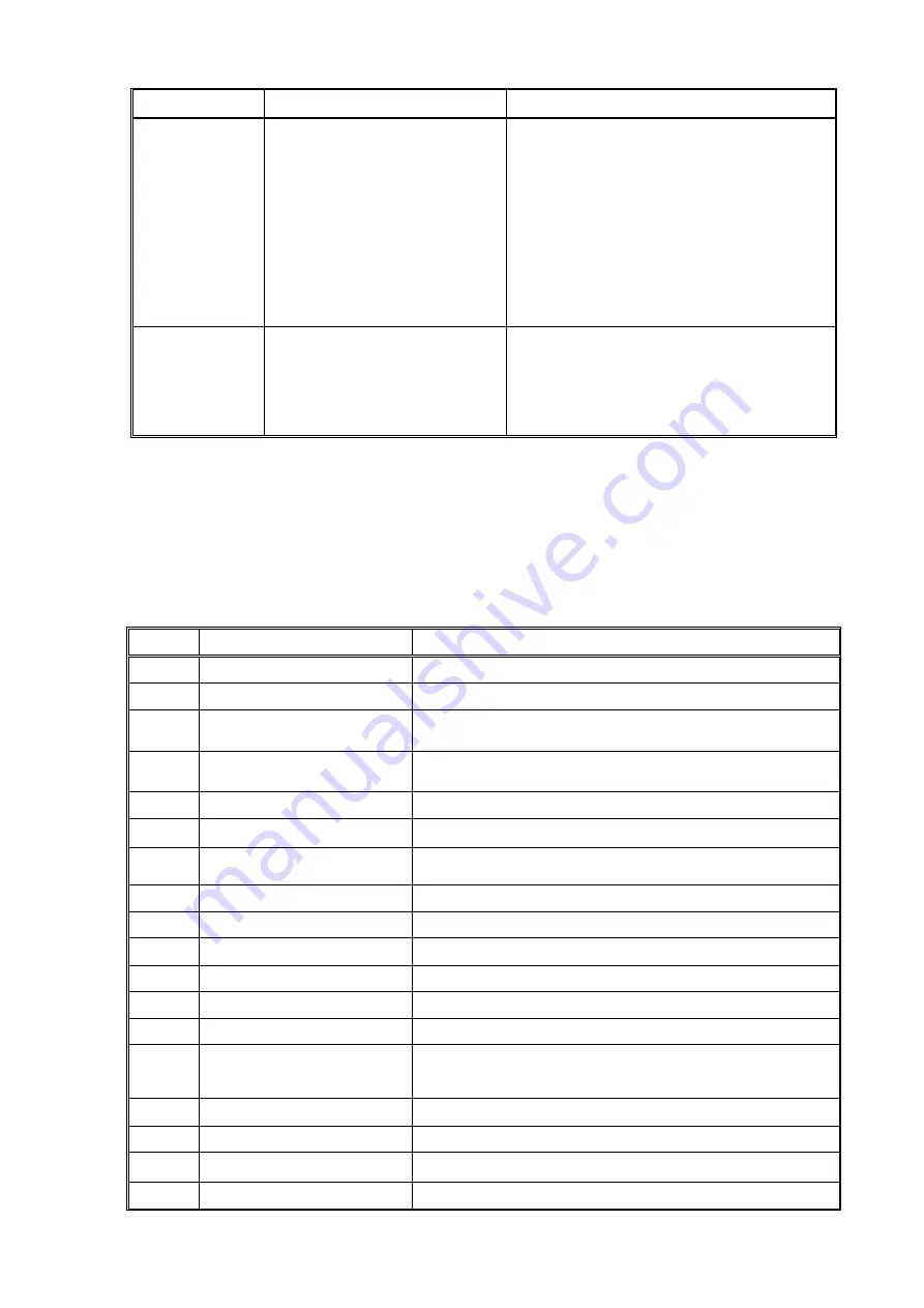
Phenomenon
Reason
Measurement
Short life for
consumables
1
、
Big difference between the actually
gas pressure and theory gas pressure.
2
、
nozzle to workpiece distance too
small
(<
2mm
)
3
、
nozzle diameter not match the
current.
4
、
Workpiece too thickness.
5
、
Electrode and nozzle quality
problem.
1
、
Check and adjust the air pressure accordingly
2
、
increase the distance between torch and workpiece.
3
、
Choose the correct diameter nozzle according to
using current.
4
、。
Workpiece thickness shall be in the range of quality
cutting thickness.
5
、
Replace electrode and nozzle.
Power supply
switch trip
1
、
Rectifier bridge is broken.
2
、
IGBT broken.
3
、
Main circuit other parts broken.
4. Air breaker capacity too small
1
、
replace same model rectifier bridge.
2
、
Replace same model IGBT module.
3
、
Check and replace the damaged parts.
4. Change a bigger capacity breaker
Note:Please record the phenomenon of trouble shooting,if not able to repair,please contact our local agent or contact
Huayuan manufacture directly. Also provide the model and series number of the power source(refer to nameplate).
4. Control panel indicator instruction
On PCB PL18 and PL02 have the LED indicator, problem can be solved according to the status of the indicator
1)
PCB PL18
LED code
Indicator function
Instruction
LED1
+15V3
+15V3 power supply normal
LED2
-15V1
-15V1 power supply normal
LED3
Coolant high level
LED on when coolant more than high level
LED4
Coolant low level
LED on when coolant less than low level
LED5
+24V
+24V power supply normal
LED6
Lack voltage
Power source input voltage lower than 85% of the rated input voltage
LED7
+15V2
+15V2 power supply normal
LED8
-15VD2
-15V2 power supply normal
LED9
+5V_T
+5V_T power supply normal
LED10
Over voltage
Power source input voltage higher than 15% of the rated input voltage
LED11
+5V
+5V power supply normal
LED12
+15V1
+15V1 power supply normal
LED13
Start pilot arc
Pilot arc signal On
LED14
Current adjust remote control
identify signal
Input current adjust remote control identify signal to X5 at back of the
machine,LED14 on
LED15
+15V
+15V power supply normal
LED16
Remote control gas check signal
Input gas check signal to X5 at back of the machine, LED16 on
LED17
Start signal
Machine receive start signal, LED17 on
LED18
corner signal
Machine receive corner signal,LED18 on
Summary of Contents for SLG-200HF
Page 12: ...5 3 2 SLG 300HF dimension and weight 3 3 SLG 400HF dimension and weight...
Page 22: ...15 5 2 Installation Drawing System components A Plasma power sourceSLG 200HF 300HF 400HF...
Page 47: ...40 3 Circuit diagram 7 1 SLG 200HF...
Page 48: ...41 7 2 SLG 300HF...
Page 49: ...42 7 3 SLG 400HF...
Page 50: ...43 7 4 QFK E1...