


18
9. Torch installation
(
5-2 Part C
)
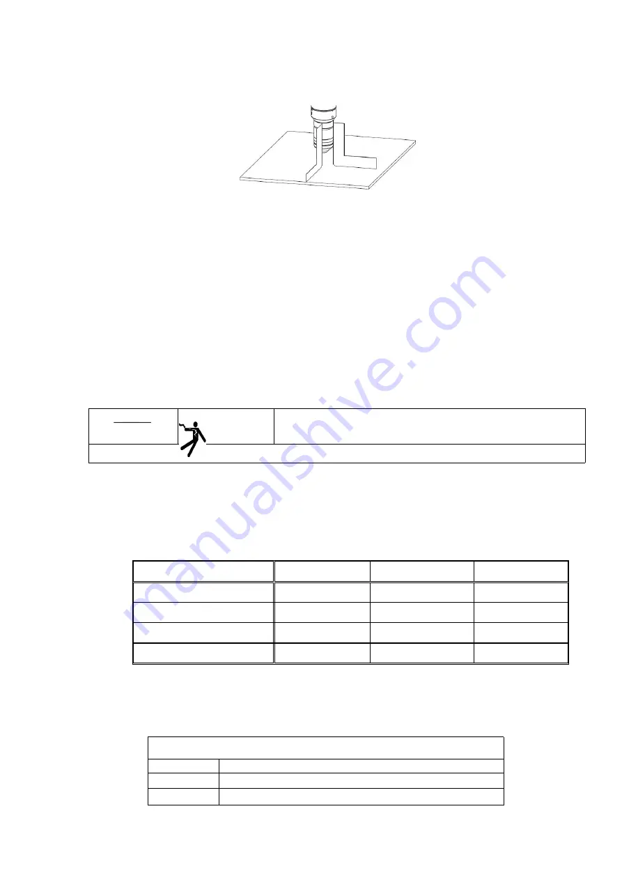
1. Torch install on the CNC table
Install the torch in the tray
Encase the bottom of the torch sleeve by bracket, but do not touch the torch quick knockdown connector. Try to
clamp the lower position of the torch sleeve as far as possible, to reduce the vibration of the torch mouth.
Fasten the fixed screws.
Torch Alignment.see Fig 11,use a right corner gauge to make the torch at right corners to the workpiece.
2
、
Requirements for the torch lifting device
The cutting system require a good quality electric torch lifting device, which should have 203mm stroke and
max.5080mm/min constant speed with good brake function.
10. Cable and hose installation
(
5-2
○
1
~
○
18
)
○
1
Power supply cable
Danger
Shock may cause people die
When install the cable, the switch must be OFF
a)
Take off the back cover, install the power cable to the power connect box
b)
Connect the PE cable to the ground connect terminal on machine back
c)
Make sure the switch in OFF
d)
Connect all cable and hose according to the state standard
4-1 Power cable requirements
Item
SLG-200HF
SLG-300HF
SLG-400HF
Power supply cable square meter
≥16 mm
2
≥35 mm
2
≥50 mm
2
Ground cable square meter
≥16 mm
2
≥16 mm
2
≥25 mm
2
Air breaker capacity
125A
160A
250A
Fuse capacity
125A
150A
200A
○
2
Arc voltage output cable
(
5-2
○
2
)
Cutting power source arc voltage output plug X3 connect with the outside THC, the X3 plug signal is 1:1
non-isolated arc voltage
Arc voltage cable pin signal
Pin
Signal
1
Arc voltage
2
Arc voltage signal-
Summary of Contents for SLG-200HF
Page 12: ...5 3 2 SLG 300HF dimension and weight 3 3 SLG 400HF dimension and weight...
Page 22: ...15 5 2 Installation Drawing System components A Plasma power sourceSLG 200HF 300HF 400HF...
Page 47: ...40 3 Circuit diagram 7 1 SLG 200HF...
Page 48: ...41 7 2 SLG 300HF...
Page 49: ...42 7 3 SLG 400HF...
Page 50: ...43 7 4 QFK E1...