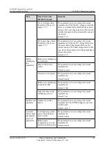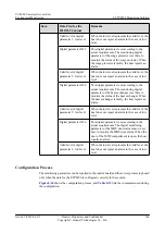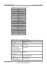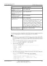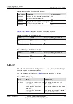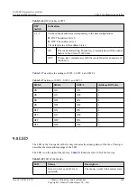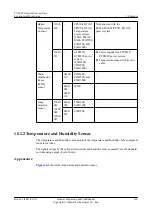
LED
Status
Description
Yellow: on
The communication is lost.
Red: on for 0.3s and off for 0.3s
repeatedly
The fan tray is faulty, or it generates an
alarm when the temperature is very
high.
9.5 DIP Switch
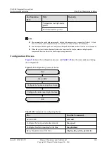
The fan tray is configured with the fan monitoring board that provides one set of DIP switches.
This topic provides the indications and settings of the DIP switches on the fan tray.
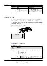
The H801FCBB monitoring board of the fan tray provides a set of DIP switches: SW2.
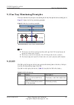
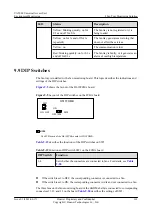
Figure 9-3
Layout of SW2 (default settings)
H801FCBB
ON
5
6
7
8
1
2
3
4
SW2
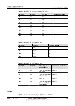
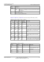
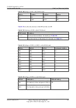
describes the settings of SW2.
Table 9-10
Settings of SW2
DIP
Switch
Indication
1, 2, 3
Set the corresponding subnode addresses corresponding to the data
configuration.
l
ON: The address bit is 0.
l
OFF: The address bit 1.
The default value of the address bit is 1.
4
ON
The fan tray communicates with the control board at a baud rate
of 19200 bit/s. This is the default setting.
UA5000 Universal Access Unit
Environment Monitoring
9 Fan Tray Monitoring Solution
Issue 01 (2012-08-17)
Huawei Proprietary and Confidential
Copyright © Huawei Technologies Co., Ltd.
156

