5 Removing and replacing components
Tecal RH5485 Server
Problem Determination and Service Guide
5-68
Huawei Proprietary and Confidential
Copyright © Huawei Technologies Co., Ltd.
Issue 02 (2011-05-25)
Step 8
Disconnect the signal cables from the ServeRAID adapter and remove the adapter from the
server (see “Removing the RAID adapter carrier and the RAID adapter assembly”).
Step 9
Remove the middle fan (see “Removing the middle hot-swap fan”).
Step 10
Remove the memory-card cage (see “Removing the memory-card cage”).
Step 11
Disconnect the following cables: front fan, scalability LED, operator information panel, hard
disk drive backplane, and CD/DVD power.
Step 12
(Trained service technician only) Remove the microprocessors (see “Removing a
microprocessor and heat sink”).
Step 13
Remove the QPI wrap cards or fillers (see “Removing a QPI wrap card”).
Step 14
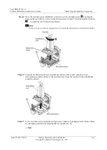
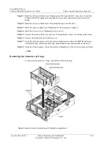
Loosen the thumbscrews on the rear of the server.
Step 15
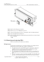
Slide the assembly slightly toward the front of the server; then, using the microprocessor
board handle on the left side, lift the assembly out at an angle.
Step 16
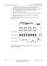
Remove the microprocessor socket covers from the new microprocessor-board assembly and
install them on the empty microprocessor sockets on the old microprocessor board before
packing the board for shipping.
Step 17
If you are instructed to return the microprocessor-board assembly, follow all packaging
instructions, and use any packaging materials for shipping that are supplied to you.
----End
Replacing the microprocessor-board assembly
To install the replacement microprocessor-board assembly, complete the following steps:
Step 1
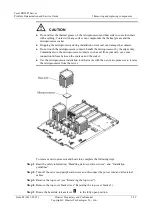
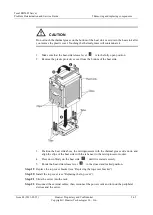
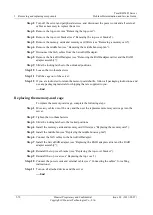
Insert the microprocessor-board assembly in the server at an angle; then, slide the assembly
toward the back of the server. Make sure that all the cables are clear of the assembly as you
install it in the server.
Step 2
Tighten the thumbscrews on the rear of the server.
Step 3
Install the QPI wrap cards or fillers.
Step 4
Connect the following cables: front fan, scalability LED, operator information panel, hard
disk drive backplane, and CD/DVD power.
Step 5
Route the front USB and DVD/CD signal cables behind the hard disk drive backplane and to
the side of the ServeRAID adapter connector (see “Internal cable routing and connectors”).
Step 6
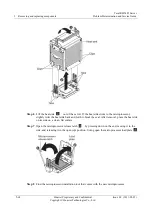
(Trained service technician only) Reinstall the microprocessors (see “Installing a
microprocessor and heat sink”).
Step 7
Install the memory-card cage (see “Replacing the memory-card cage”). Make sure that all the
cables are clear of the cage as you install it in the server.
Step 8
Install the middle fan (see “Replacing the middle hot-swap fan”).
Step 9
Connect the signal cables to the ServeRAID adapter and install the adapter in the server (see
“Replacing the RAID adapter carrier and the RAID adapter assembly”).
Step 10
Install the memory cards and memory card fillers (see “Replacing the memory card”).


