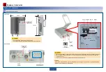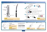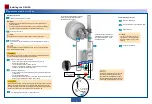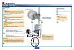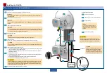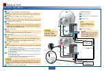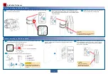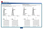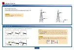
Hole 2 (-): Insert a blue -48 V cable into
it.
Ensure that the cable section inserted into each hole is
at least 11 mm in length.
Hole 1 (+): Insert a brown (black) 0 V ground cable into it.
Red cable
locking latch
Blue cable locking latch
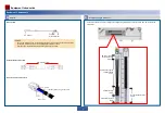
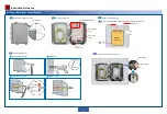
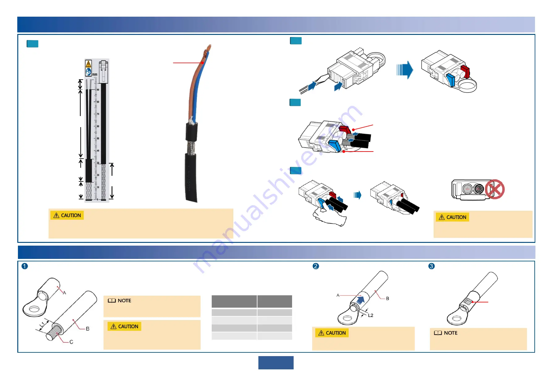
Strip power cables based on the scale.
Insert the power cables.
Push the cable locking latches on both sides back. Slightly pull the power cables to check whether they are
connected securely.
Use a screwdriver to poke the cable locking latches out.
•
A cable must be inserted in the center of a hole.
•
A cable must be perpendicular to a hole.
A cable must be inserted in the center of a hole.
Ensure that the positive and negative cables are correctly connected.
1
3
2
4
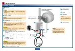
Avoid dropping any miscellaneous objects (especially metal scraps) in the maintenance
compartment. Clean up them immediately if any.
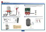
W ires exposed
8 mm
Outdoor network cable
29 mm
Sheath reserved
19 mm
DC power cable
Positive and negative
cables exposed
57 mm
W ires
7
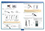
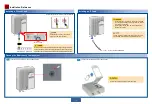
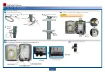
Terminating a Ground Cable with an OT Terminal
Strip the ground cable.
A: OT terminal
B: ground cable
C: exposed cable conductor
L1: length of the exposed cable
Fit the exposed cable into the OT terminal.
Crimp the OT terminal lug.
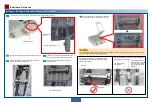
Mapping between the cross-sectional
area of a cable conductor (C) and the
length of an exposed cable (L1)
Crimp the OT
terminal lug.
Cross-sectional
Area of C (mm
2
)
L1 (mm)
1
7
1.5
7
2.5
7
4
8
When you are skillful, you can determine L1
based on the length of the OT terminal lug.
When striping off the insulation layer of the
ground cable, take care not to damage or nick
the metal conductor of the cable.
Ensure that the cable conductor does not protrude
more than 2 mm from the OT terminal.
The crimping impression may differ depending
on the crimping tool used.
Terminating Power Cables with a Tool-Less DC Power Connector
If the wires slide outward or are exposed outside the holes, remove
the cables and cut the wires. Then strip and connect the cables again.


