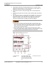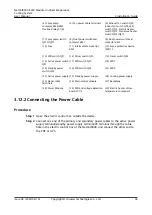
(4) Spray pump
contactor KM4/KM5,
Overload relay K1/K2
(5) Fan power cable terminals
(6) Exhaust fan switch QF8,
Indoor fan switch QF9, LED
switch QF12, Electric heater
switch QF13, Crankcase heater
switch QF14/QF15
(7) Spray pump switch
QF10/QF11
(8) Dual power switchover
contactor KM1
(9) Dual power switchover
contactor KM2
(10) Fuse
(11) Intermediate contactor
KM3
(12) Surge protective device
(SPD) 3
(13) SPD switch QF7
(14) Driver switch QF5
(15) Driver switch QF6
(16) Active power switch
QF1
(17) SPD switch QF3
(18) SPD1
(19) Standby power
switch QF2
(20) SPD switch QF4
(21) SPD2
(22) Active power supply (23) Standby power supply
(24) Cooling power supply
(25) Signal cable
terminals
(26) Main control module
(27) Backplane
(28) Power Module
(29) SPD and voltage detection
board FV1/2
(30) Electric heater of low-
temperature component
3.12.2 Connecting the Power Cable
Procedure
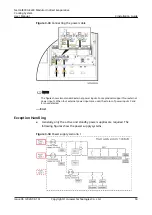
Step 1 Open the electric control box outside the device.
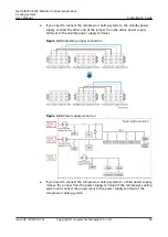
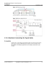
Step 2 Connect one end of the primary and secondary power cables to the active power
supply terminal/standby power supply terminal/PE terminal through the cable
hole in the electric control box of the NetCol8000, and connect the other end to
the PDF or UPS.
NetCol8000-E220 Modular Indirect Evaporative
Cooling System
User Manual
3 Installation Guide
Issue 06 (2020-08-19)
Copyright © Huawei Technologies Co., Ltd.
58

