background image


10 

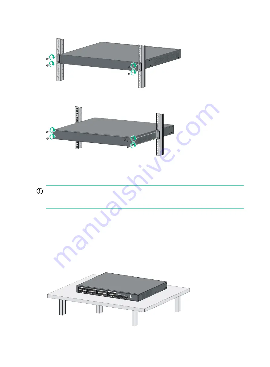
Figure 10 Mounting an HPE 5130 24G SFP 4SFP+ EI switch by the rear mounting position 


Figure 11 Mounting an HPE 5130 24G SFP 4SFP+ EI switch by the mid-mounting position 


Mounting the switch on a workbench 


IMPORTANT: 

  Ensure 10 cm (3.9 in) of clearance around the chassis for heat dissipation. 

  Do not place heavy objects on the switch. 


If a standard 19-inch rack is not available, you can place you switch on a workbench. 

To mount the switch on a workbench:  

1. 

Verify that the workbench is sturdy and reliably grounded. 

2. 

Place the switch with bottom up, and clean the round holes in the chassis bottom with dry cloth. 

3. 

Attach the rubber feet to the four round holes in the chassis bottom. 

4. 

Place the switch with upside up on the workbench. 

Figure 12 Mounting the switch on a workbench 


Summary of Contents for FlexNetwork 5130 EISeries

Page 1: ...HPE FlexNetwork 5130 EI Switch Series Installation Guide Part number 5998 5492s Document version 6W104 20160930 ...

Page 2: ...nd 12 212 Commercial Computer Software Computer Software Documentation and Technical Data for Commercial Items are licensed to the U S Government under vendor s standard commercial license Links to third party websites take you outside the Hewlett Packard Enterprise website Hewlett Packard Enterprise has no control over and is not responsible for information outside the Hewlett Packard Enterprise ...

Page 3: ...ce 16 Connecting the switch to a 48 VDC power source 17 Connecting the switch to an RPS 18 Verifying the installation 19 Accessing the switch for the first time 20 Setting up the configuration environment 20 Connecting the console cable 20 Setting terminal parameters 21 Powering on the switch 21 Setting up an IRF fabric 22 IRF fabric setup flowchart 22 Planning IRF fabric setup 23 Planning IRF fab...

Page 4: ...Ports 42 Console port 42 10 100 1000Base T autosensing Ethernet port 42 1 10GBase T autosensing Ethernet port 42 100 1000Base X SFP port 43 SFP port 45 Combo interface 46 LEDs 46 System status LED 46 Power supply status LED 46 RPS status LED 47 Port mode LED 47 10 100 1000Base T autosensing Ethernet port LED 47 1 10GBase T autosensing Ethernet port LEDs 50 100 1000Base X SFP port LED 199H51 83HSFP...

Page 5: ...48G 4SFP EI BR JG977A HPE FlexNetwork 5130 24G PoE 4SFP 370W EI Brazil Switch HPE 5130 24G PoE 4SFP 370W EI BR JG978A HPE FlexNetwork 5130 48G PoE 4SFP 370W EI Brazil Switch HPE 5130 48G PoE 4SFP 370W EI BR Power supplies applies only to the JG933A switch JD362A HPE A5800 A5500 150W AC Power Supply PSR150 A JD362B HPE X361 150W AC Power Supply PSR150 A1 JD366A HPE A5800 A5500 150W DC Power Supply ...

Page 6: ...power cords from the switch Do not clean the switch with wet cloth or liquid Do not place the switch near water or in a damp environment Prevent water or moisture from entering the switch chassis Do not place the switch on an unstable case or desk Ensure good ventilation at the installation site and keep the air inlet and outlet vents of the switch free of obstruction Connect the yellow green prot...

Page 7: ...ative humidity is low In the worst case electrostatic adsorption can cause communication failure Table 1 Dust concentration limit in the equipment room Substance Concentration limit particles m Dust 3 x 10 4 no visible dust on the tabletop over three days NOTE Dust diameter 5 μm The equipment room must also meet limits on salts acids and sulfides to eliminate corrosion and premature aging of compo...

Page 8: ...rewdriver ESD wrist strap All these installation tools are user supplied Installation accessories Table 3 Installation accessories Product code Description Quantity Applicable models 5066 0850 1 U four hole mounting bracket kit including one pair of mounting brackets and eight M4 countersunk screws 1 kit HPE 5130 24G PoE 4SFP 370W EI HPE 5130 48G 4SFP EI HPE 5130 48G PoE 4SFP 370W EI HPE 5130 24G ...

Page 9: ...0W EI HPE 5130 24G PoE 2SFP 2XGT 370W EI HPE 5130 48G PoE 2SFP 2XGT 370W EI HPE 5130 24G PoE 4SFP 370W EI BR HPE 5130 48G PoE 4SFP 370W EI BR 5185 9443 5080 0120 DC power cord supplied with the PSR150 D PSR150 D1 JD366A JD366B DC power supply The power cord color code scheme is for illustration only The cable delivered for your country or region might use a different color scheme 1 PSR150 D PSR150...

Page 10: ... you want to open the chassis contact Hewlett Packard Enterprise for permission Otherwise Hewlett Packard Enterprise shall not be liable for any consequence Figure 1 Hardware installation flow Installing the switch in a 19 inch rack Mounting brackets Table 4 describes the mounting brackets provided with the switch ...

Page 11: ...0W EI BR HPE 5130 48G PoE 4SFP 370W EI BR One pair of 1U four hole mounting brackets See Figure 3 Figure 2 1U two hole mounting bracket 1 Screw hole for attaching the bracket to the switch 2 Screw hole for attaching the bracket to the rack post Figure 3 1U four hole mounting bracket 1 Screw hole for attaching the bracket to the switch 2 Screw hole for attaching the bracket to the rack post Attachi...

Page 12: ...wer supplies To attach the mounting brackets to the switch 1 Determine the mounting position 2 Align one mounting bracket with the screw holes at the mounting position Use M4 screws provided with the switch to attach the mounting bracket to the chassis 3 Repeat step 2 to attach the other mounting bracket to the chassis Figure 4 Attaching a two hole mounting bracket to the front mounting position o...

Page 13: ...make sure it makes good skin contact and is reliably grounded 2 Verify that the mounting brackets have been securely attached to the switch chassis 3 Install cage nuts in the mounting holes in the rack posts 4 One person holds the switch chassis and aligns the mounting brackets with the mounting holes in the rack posts and the other person attaches the mounting brackets with screws user supplied t...

Page 14: ...on Do not place heavy objects on the switch If a standard 19 inch rack is not available you can place you switch on a workbench To mount the switch on a workbench 1 Verify that the workbench is sturdy and reliably grounded 2 Place the switch with bottom up and clean the round holes in the chassis bottom with dry cloth 3 Attach the rubber feet to the four round holes in the chassis bottom 4 Place t...

Page 15: ...conductor buried in the earth ground Grounding the switch by using the PE wire of the AC power cord NOTE The power and grounding terminals in this section are for illustration only Grounding the switch with a grounding strip WARNING Connect the grounding cable to the grounding system in the equipment room Do not connect it to a fire main or lightning rod If a grounding strip is available at the in...

Page 16: ...the cable to the post Figure 14 Connecting the grounding cable to a grounding strip 1 Grounding post 2 Grounding strip 3 Grounding cable 4 Hex nut Grounding the switch with a grounding conductor buried in the earth ground If the installation site has no grounding strips but earth ground is available hammer a 0 5 m 1 64 ft or longer angle iron or steel tube into the earth ground to serve as a groun...

Page 17: ... the problem and reconstruct the grounding system NOTE To guarantee the grounding effect use the grounding cable provided with the switch to connect to the grounding strip in the equipment room as long as possible Installing and removing a power supply HPE 5130 24G SFP 4SFP EI switch CAUTION Provide a circuit breaker for each power supply and make sure the circuit breaker is off before installatio...

Page 18: ... the upside up Grasp the handle of the power supply with one hand and support its bottom with the other and slide the power supply slowly along the guide rails into the slot See callout 1 in Figure 18 To prevent damage to the power supply and the connector on the switch backplane insert the power supply gently If you encounter a hard resistance or the power supply tilts while inserting the power s...

Page 19: ... the power cord make sure the circuit breaker on the power cord is turned off Table 5 Power cord connection procedures at a glance Switch model Available power source Connection procedure reference HPE 5130 24G 4SFP EI HPE 5130 24G 2SFP 2XGT EI HPE 5130 24G 4SFP EI BR AC power source Connecting the switch to an AC power source HPE 5130 48G 4SFP EI HPE 5130 24G SFP 4SFP EI HPE 5130 48G 2SFP 2XGT EI...

Page 20: ... input The PSR150 D PSR150 D1 JD366A JD366B power supply supports 48 V DC power input and RPS power input Connecting the switch to an AC power source Securing the AC power cord for a hot swappable AC power supply 1 Insert the cable tie through the hole in the power supply handle 2 Use the cable tie to secure the AC power cord to the power supply handle Figure 20 Securing the AC power cord for a ho...

Page 21: ...n its wires To connect the switch to a 48 VDC power source 1 Wear an ESD wrist strap and make sure it makes good skin contact and is reliably grounded 2 Insert the DC connector into the DC power receptacle See callout 1 in Figure 23 The connector of the DC power cord and the DC power receptacle are foolproof Make sure the connector is correctly oriented 3 Use a flat blade screwdriver to fasten the...

Page 22: ...h the power receptacle on the power supply and insert the plug into the receptacle See callout 1 in Figure 23 If you cannot insert the plug into the receptacle re orient the plug rather than use excessive force to push it in 2 Tighten the screws on the plug with a flat blade screwdriver to secure the plug in the RPS receptacle See callout 2 in Figure 23 3 Connect the other end of the power cord to...

Page 23: ...e rack or workbench is stable The grounding cable is securely connected The correct power source is used The power cords are correctly connected All the interface cables are cabled indoors If any cable is routed outdoors verify that the socket strip with lightning protection and lightning arresters for network ports have been correctly connected ...

Page 24: ...ing the console port to a terminal Connecting the console cable A console cable is an 8 core shielded cable with a crimped RJ 45 connector at one end for connecting to the console port of the switch and a DB 9 female connector at the other end for connecting to the serial port on the configuration terminal Figure 26 Console cable Table 6 Console cable pinouts RJ 45 Signal DB 9 Signal 1 RTS 8 CTS 2...

Page 25: ...the required terminal settings Bits per second 9 600 Data bits 8 Stop bits 1 Parity None Flow control None Powering on the switch Before powering on the switch verify that the following conditions are met The power cord is correctly connected The input power voltage meets the requirement of the switch The console cable is correctly connected The configuration terminal a PC for example has started ...

Page 26: ...gure 27 IRF fabric setup flowchart To set up an IRF fabric Step Description 1 Plan IRF fabric setup Plan the installation site and IRF fabric setup parameters Planning IRF fabric size and the installation site Identifying the master switch and planning IRF member IDs Planning IRF topology and connections Identifying physical IRF ports on the member switches Planning the cabling scheme 2 Install IR...

Page 27: ... member switches in different racks to implement the ToR access solution for a data center Identifying the master switch and planning IRF member IDs Determine which switch you want to use as the master for managing all member switches in the IRF fabric An IRF fabric has only one master switch You configure and manage all member switches in the IRF fabric at the CLI of the master switch IRF member ...

Page 28: ...switches The IRF port connections in the two figures are for illustration only and more connection methods are available Figure 28 IRF fabric in daisy chain topology Figure 29 IRF fabric in ring topology Identifying physical IRF ports on the member switches Identify the physical IRF ports on the member switches according to your topology and connection scheme Planning the cabling scheme Use twiste...

Page 29: ...cting the IRF member switches in one rack Use SFP cables to connect the IRF member switches 9 switches in this example in a rack as shown in Figure 30 The switches in the ring topology see Figure 31 are in the same order as connected in the rack Figure 30 Connecting the switches in one rack 1 2 3 4 5 6 7 8 9 1 2 3 4 5 6 7 8 9 ...

Page 30: ...these guidelines when you configure the switches Assign the master switch higher member priority than any other switch Bind physical ports to IRF port 1 on one switch and to IRF port 2 on the other switch You perform IRF port binding before or after connecting IRF physical ports depending on the software release Execute the display irf configuration command to verify the basic IRF settings For mor...

Page 31: ...fy that you can manage all member switches as if they were one node 5 Display the running status of the IRF fabric by using the commands in Table 7 Table 7 Displaying and maintaining IRF configuration and running status Task Command Display information about the IRF fabric display irf Display all members IRF configurations that take effect at a reboot display irf configuration Display IRF fabric t...

Page 32: ...e examine the system status LED and the RPS status LED of the switch Table 8 Fixed power supply LED description LED Mark Status Description System status LED SYS Off The switch is powered off RPS status LED RPS Steady green The AC input is normal and the RPS is in position or working normally Steady yellow RPS power input is normal but AC input has failed or AC input is not connected Off No RPS is...

Page 33: ...AC power cord is securely connected to the switch and the AC input power receptacle on the switch and the connected AC power outlet are in good condition 2 Verify that the AC power source is operating correctly 3 Verify that the switch is securely connected to the RPS 4 Verify that the RPS is operating correctly 5 Verify that the operating temperature of the switch is in the acceptable range and t...

Page 34: ...e range 4 If the problem persists contact Hewlett Packard Enterprise Support Configuration terminal problems No display on the configuration terminal Symptom The configuration terminal does not display any information when the switch is powered on Solution To resolve the problem 1 Verify that the power system is operating correctly 2 Verify that the switch is operating correctly 3 Verify that the ...

Page 35: ...ve the problem 1 Verify that the following settings are configured for the terminal Baud rate 9600 Data bits 8 Parity None Stop bits 1 Flow control None 2 If the problem persists contact Hewlett Packard Enterprise Support ...

Page 36: ...se T autosensing Ethernet port 2 SFP port 3 Console port 4 10 100 1000Base T autosensing Ethernet port LED 5 SFP port LED 6 System status LED SYS Figure 34 Rear panel 1 AC input power receptacle 2 Grounding screw HPE 5130 24G PoE 4SFP 370W EI HPE 5130 24G PoE 4SFP 370W EI BR Figure 35 Front panel 1 10 100 1000Base T autosensing Ethernet port 2 SFP port ...

Page 37: ...re 36 Rear panel 1 AC input power receptacle 2 RPS receptacle 3 Grounding screw HPE 5130 24G 2SFP 2XGT EI Figure 37 Front panel 1 10 100 1000Base T autosensing Ethernet port 2 SFP port 3 1 10GBase T autosensing Ethernet port 4 Console port 5 10 100 1000Base T autosensing Ethernet port LED 6 SFP port LED 7 System status LED SYS 8 1 10GBase T autosensing Ethernet port LED Figure 38 Rear panel 1 AC i...

Page 38: ... 7 SFP port LED 8 System status LED SYS 9 RPS status LED RPS 10 1 10GBase T autosensing Ethernet port LED 11 Port mode LED Figure 40 Rear panel 1 AC input power receptacle 2 RPS receptacle 3 Grounding screw HPE 5130 48G 4SFP EI HPE 5130 48G 4SFP EI BR Figure 41 Front panel 1 10 100 1000Base T autosensing Ethernet port 2 10 100 1000Base T autosensing Ethernet port LED 3 Console port 4 SFP port LED ...

Page 39: ...igure 43 Front panel 1 10 100 1000Base T autosensing Ethernet port 2 10 100 1000Base T autosensing Ethernet port LED 3 Console port 4 SFP port 5 Port LED mode switching button 6 Port mode LED 7 System status LED SYS 8 RPS status LED RPS 9 SFP port LED Figure 44 Rear panel 1 Grounding screw 2 AC input power receptacle 3 RPS receptacle 7 1 2 3 4 5 6 8 9 ...

Page 40: ...hernet port LED 9 SFP port LED Figure 46 Rear panel 1 AC input power receptacle 2 RPS receptacle 3 Grounding screw HPE 5130 48G PoE 2SFP 2XGT 370W EI Figure 47 Front panel 1 10 100 1000Base T autosensing Ethernet port 2 10 100 1000Base T autosensing Ethernet port LED 3 SFP port 4 Console port 5 Port LED mode switching button 6 Port mode LED 7 System status LED SYS 8 RPS status LED RPS 9 1 10GBase ...

Page 41: ...pply 1 status LED PWR1 10 Power supply 2 status LED PWR2 Figure 50 Rear panel 1 Grounding screw 2 Power supply slot 1 3 Power supply slot 2 The HPE 5130 24G SFP 4SFP EI switch comes with no power supply or filler panel in power supply slot 1 and a filler panel in power supply slot 2 You can install one or two power supplies for the switch as needed In Figure 50 two PSR150 A1 JD362B AC power suppli...

Page 42: ...and its corresponding SFP port form a combo interface 48 1 10GBase T autosensing Ethernet ports N A 2 N A N A 2 100 1000Ba se X SFP ports N A N A N A 24 The rightmost eight SFP ports and their corresponding 10 100 1000Ba se T autosensing Ethernet ports form combo interfaces N A SFP ports 4 2 4 4 2 Power supply slots N A N A N A 2 on the rear panel N A Input voltage Rated voltage 100 VAC to 240 VAC...

Page 43: ... 32 F to 113 F Operating humidity 5 to 95 noncondensing Fire resistance compliance UL60950 1 EN60950 1 IEC60950 1 GB4943 1 Table 10 Technical specifications for PoE switch models Item HPE 5130 24G PoE 2SFP 2XGT 370W EI HPE 5130 24G PoE 4SFP 370W EI HPE 5130 24G PoE 4SFP 370W EI BR HPE 5130 48G PoE 4SFP 370W EI HPE 5130 48G PoE 4SFP 370W EI BR HPE 5130 48G PoE 2SFP 2XGT 370W EI Dimensions H W D 43 ...

Page 44: ... power consumptio n AC 31 W DC 20 W AC 30 W DC 25 W AC 47 W DC 43 W AC 43 W DC 30 W Maximum power consumptio n including PoE consumptio n AC 425 W including 370 W PoE consumption DC 770 W including 740 W PoE consumption AC 460 W including 370 W PoE consumption DC 790 W including 740 W PoE consumption AC 490 W including 370 W PoE consumption DC 890 W including 800 W PoE consumption AC 470 W includi...

Page 45: ...cification Remarks PSR150 A JD362A PSR150 A1 JD362B Rated input voltage 100 VAC to 240 VAC 50 Hz or 60 Hz For more information about the power supplies see HPE PSR150 A PSR150 D Power Supplies User Guide Max input voltage 90 VAC to 264 VAC 47 Hz to 63 Hz Max output power 150 W PSR150 D JD366A PSR150 D1 JD366B Rated input voltage 48 VDC to 60 VDC Max input voltage 36 VDC to 72 VDC Max output power ...

Page 46: ...s Table 13 10 100 1000Base T autosensing Ethernet port specifications Item Specification Connector type RJ 45 Interface attributes 10 100 1000 Mbps half full duplex MDI MDI X autosensing Max transmission distance 100 m 328 08 ft Transmission medium Category 5 or above twisted pair cable Compatible standards IEEE 802 3i 802 3u 802 3ab 1 10GBase T autosensing Ethernet port The HPE 5130 24G 2SFP 2XGT...

Page 47: ...bution frame 1 and port 2 on the device to port 1 on distribution frame 2 Keep the device and twisted pair cables away from the interference source such as a two way radio and a high power variable frequency drive 100 1000Base X SFP port The HPE 5130 24G SFP 4SFP EI switch provides 24 100 1000Base X SFP ports and you can install the 100 Mbps SFP transceiver modules in Table 15 and 1000 Mbps SFP tr...

Page 48: ...10 LC Single mode 9 125 N A 10 km 6 21 miles Multi mode 50 125 500 or 400 550 m 1804 46 ft Multi mode 62 5 125 500 550 m 1804 46 ft JD061A HPE X125 1G SFP LC LH40 1310nm Transceiver 1310 LC Single mode 9 125 N A 40 km 24 86 miles JD062A HPE X120 1G SFP LC LH40 1550nm Transceiver 1550 LC Single mode 9 125 N A 40 km 24 86 miles JD063B HPE X125 1G SFP LC LH70 Transceiver 1550 LC Single mode 9 125 N A...

Page 49: ...85 30 ft JD094B HPE X130 10G SFP LC LR Transceiver 1310 LC Single mode 9 125 N A 10 km 6 21 miles Table 18 SFP cables available for the SFP ports Product code HPE description Max transmission distance JD095C HPE X240 10G SFP SFP 0 65m DA Cable 0 65 m 2 13 ft JD096C HPE X240 10G SFP SFP 1 2m DA Cable 1 2 m 3 94 ft JD097C HPE X240 10G SFP SFP 3m DA Cable 3 m 9 84 ft JG081C HPE X240 10G SFP SFP 5m DA...

Page 50: ...atus LED shows the operating status of the switch Table 19 System status LED description LED mark Status Description SYS Steady green The switch is operating correctly Flashing green The switch is performing power on self test POST Steady red The switch has failed POST Flashing yellow Some ports have failed POST Off The switch is powered off Power supply status LED The HPE 5130 24G SFP 4SFP EI swi...

Page 51: ...escription RPS Steady green Both the RPS DC input and the AC input are normal Steady yellow The RPS DC input is normal but the AC input is disconnected or has failed Off The RPS DC input has failed or no RPS is connected Port mode LED The HPE 5130 24G PoE 2SFP 2XGT 370W EI HPE 5130 48G PoE 2SFP 2XGT 370W EI HPE 5130 24G PoE 4SFP 370W EI HPE 5130 24G PoE 4SFP 370W EI BR HPE 5130 48G PoE 4SFP 370W E...

Page 52: ...E 4SFP 370W EI BR HPE 5130 48G PoE 2SFP 2XGT 370W EI Steady green rate mode Steady green The port is operating at 1000 Mbps and a link is present on the port Flashing green The port is sending or receiving data at 1000 Mbps Steady yellow The port is operating at 10 100 Mbps and a link is present on the port Flashing yellow not 3 Hz The port is sending or receiving data at 10 100 Mbps Flashing yell...

Page 53: ... The port is operating at 10 100 Mbps and a link is present on the port Flashing not 3 Hz The port is sending or receiving data at 10 100 Mbps Flashing yellow 3 Hz The port has failed POST Off No link is present on the port or the port is not operating at 10 100 Mbps HPE 5130 24G PoE 4SFP 370W EI HPE 5130 24G PoE 4SFP 370W EI BR HPE 5130 24G PoE 2SFP 2XGT 370W EI Steady green rate mode Green LED S...

Page 54: ...0GBase T autosensing Ethernet port LEDs The HPE 5130 48G 2SFP 2XGT EI and HPE 5130 48G PoE 2SFP 2XGT 370W EI switches provide a double color green and yellow LED for each 1 10GBase T autosensing Ethernet port to indicate its operating status Table 25 1 10GBase T autosensing Ethernet port double color LED description Status Description Steady green The port is operating at 10 Gbps and a link is pre...

Page 55: ...tch models 100 1000Base X SFP port LED The HPE 5130 24G SFP 4SFP EI switch provides a double color green and yellow LED for each 100 1000Base X SFP port to show its operating status Table 27 100 1000Base X SFP port LED description Status Description Steady green A transceiver module is installed in the port The port is operating at 1 Gbps and a link is present on the port Flashing green The port i...

Page 56: ...oE 4SFP 370W EI and HPE 5130 24G PoE 4SFP 370W EI BR switches provide two single color LEDs for each SFP port to indicate its operating status Table 29 Description for the two single color LEDs for the SFP port LED Status Description Green LED Steady on A transceiver module is installed in the port The port is operating at 10 Gbps and a link is present on the port Flashing The port is sending or r...

Page 57: ...e switch includes the air vents in the chassis and fixed fans To maintain good ventilation for the switch consider the ventilation design at the installation site when you plan the installation position for the switch Figure 52 Airflow through the chassis ...

Page 58: ... which you select at least one x y Asterisk marked square brackets enclose optional syntax choices separated by vertical bars from which you select one choice multiple choices or none 1 n The argument or keyword and argument combination before the ampersand sign can be entered 1 to n times A line that starts with a pound sign is comments GUI conventions Convention Description Boldface Window names...

Page 59: ...rwarding and other Layer 2 features Represents an access controller a unified wired WLAN module or the access controller engine on a unified wired WLAN switch Represents an access point Represents a wireless terminator unit Represents a wireless terminator Represents a mesh access point Represents omnidirectional signals Represents directional signals Represents a security product such as a firewa...

Page 60: ...s provide a mechanism for accessing software updates through the product interface Review your product documentation to identify the recommended software update method To download product updates go to either of the following Hewlett Packard Enterprise Support Center Get connected with updates page www hpe com support e updates Software Depot website www hpe com support softwaredepot To view and u...

Page 61: ...r self repair CSR programs allow you to repair your product If a CSR part needs to be replaced it will be shipped directly to you so that you can install it at your convenience Some parts do not qualify for CSR Your Hewlett Packard Enterprise authorized service provider will determine whether a repair can be accomplished by CSR For more information about CSR contact your local service provider or ...

Page 62: ...umber edition and publication date located on the front cover of the document For online help content include the product name product version help edition and publication date located on the legal notices page ...

Page 63: ...ting configuration terminal problems 30 verify the IRF fabric setup 27 connecting AC power source 16 console cable 20 first time switch access 20 IRF member switches in a ToR solution 26 IRF member switches in one rack 25 IRF physical ports 26 planning IRF connections 23 power cord 15 RPS 18 console connecting cable 20 port technical specifications 42 D data bits parameter 21 device troubleshootin...

Page 64: ... 43 combo interface technical specifications 46 connecting AC power source 16 connecting RPS 18 console port technical specifications 42 grounding switch 11 grounding switch through AC power supply PE wire 13 grounding switch with grounding conductor buried in the earth ground 12 grounding switch with grounding strip 11 port mode LED technical specifications 47 port technical specifications 42 pow...

Page 65: ...bench mounting switch 10 N network management maintaining the switch 28 setting up IRF fabric 22 troubleshooting configuration terminal problems 30 troubleshooting the switch 28 networking planning IRF cabling scheme 24 no terminal display troubleshooting 30 P parity parameter 21 PE wire 13 physical port connecting 26 identifying IRF member switch physical ports 24 planning IRF cabling scheme 24 2...

Page 66: ...rough AC power supply PE wire 13 grounding the switch 11 grounding the switch with grounding conductor buried in the earth ground 12 grounding the switch with grounding strip 11 installation site cleanliness 3 installation site dust concentration 3 installation site gas saturation 3 installation site humidity 3 installation site temperature 3 laser safety recommendations 4 recommendations 2 settin...

Page 67: ...interface 46 console port 42 LED 46 port 42 port mode LED 47 power supply status LED 46 RPS status LED 47 SFP port 45 SFP port LED 51 system status LED 46 temperature installation site requirements 3 terminal troubleshooting garbled terminal display 30 troubleshooting no terminal display 30 tools needed for installation 4 topology planning IRF cabling scheme 24 24 topology IRF fabric 23 troublesho...

Reviews: