96
B 215 / B 225 Evo
Operator’s manual
9. APPLYING BALANCING WEIGHTS IN
ALU1P OR ALU2P PROGRAMMES
• Adhesive weights applied with the weight-holder device (if provided) and after changing
the application position from 12 o'clock with the CLIP in the “Adhesive weight applica-
tion position” setup menu
1
Select the first side to be balanced.
2
Turn the wheel until the central element of the corresponding position indicator lights
up. Keeping the wheel in position with the clamping brake, a display will now show
the quantity of the weight to be applied in gr/ounces and the other will display the
distance in mm alternatively to the plane identification abbreviation (A-1 for Inner
Plane/A-2 for Outer Plane).
3
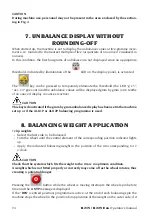
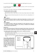
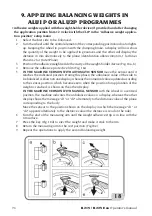
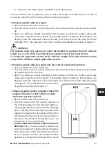
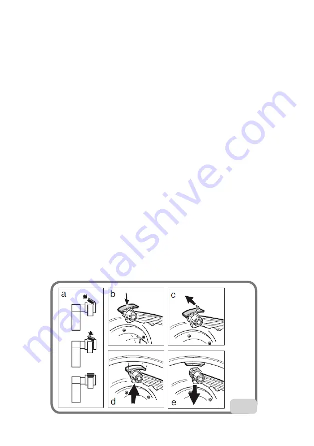
Position the adhesive weight inside the cavity of the weight-holder device (Fig. 18,a,b).
4
Remove the adhesive protective film (Fig. 18c).
5
IN THE MACHINE VERSION WITH AUTOMATIC SENSOR
move the sensor until it
reaches the indicated position. During this phase, the unbalance value of the side to
be balanced is shown on one display, whereas the numerical value updated according
to the sensor position, which becomes zero when the position for application of the
weight is reached, is shown on the other display.
IN THE MACHINE VERSION WITH MANUAL SENSOR
with the wheel in a centred
position, the machine indicates the unbalance value on a display, whereas the other
display shows the message "d1" or "d2" alternately to the distance value of the plane
corresponding to the body.
Move the sensor to the position shown on the display in which the message "d1" or
"d2" appears alternately to the distance value (the distance is read on the rule).
6
Turn the end of the measuring arm until the weight adhesive strip is in line with the
rim surface.
7
Press the key (Fig. 18d) to eject the weight and make it stick to the rim.
8
Return the measuring arm to the rest position (Fig.18e).
9
Repeat the operations to apply the second balancing weight.
18

