B 215 / B 225 Evo
Operator’s manual
85
UK
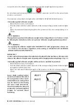
ALU 5
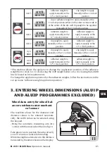
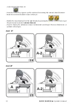
adhesive weight to
apply manually at the
12* o'clock position.
clip weight to apply
manually at the 12 o'clock
position
STA
clip or adhesive weight to apply manually at the
12 o'clock position either on the outer or inner side or
at the centre of the rim well clip weight to be applied
manually at the 12 o'clock position
ALU 1
Adhesive weight to
apply manually at the
12* o'clock position
Adhesive weight to
apply manually at the
12* o'clock position
ALU 2
clip weight to apply
manually at the 12 o'clock
position
Adhesive weight to
apply manually at the
12* o'clock position.
dyn
BIKE
clip weight to apply
manually at the 12 o'clock
position
clip weight to apply
manually at the 12 o'clock
position
ALU
BIKE
adhesive weight to
apply manually at the
12* o'clock position.
adhesive weight to
apply manually at the
12* o'clock position.
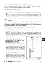
*The machine allows the operator to change the application position of the adhesive
weight from o'clock to 12 o'clock using the CLIP weight holder or 6 o'clock using the LASER
line la based on his requirements.
To change the application position for the adhesive weights, follow the instructions in the
set up menu "Adhesive weight application position ”.
3. ENTERING WHEEL DIMENSIONS (ALU1P
AND ALU2P PROGRAMMES EXCLUDED)
Wheel data entry for wheel bal-
ancers without outer mechani-
cal sensor
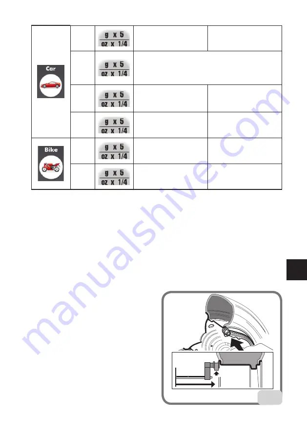
The machine allows for the diameter and
distance values to be entered automati-
cally; the width value can be entered using
the keypad.
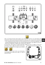
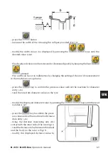
- Bring the automatic measuring arm into
contact with the inner side of the rim (fig.11).
Take great care to position the arm correctly
so as to ensure accurate data reading.
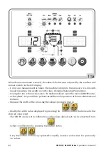
While moving the automatic arm, the distance
measured by the arm is shown on the display:
11

