


Product Overview 25
Product Over
view
DIMMs
Each array controller includes one or two ECC SDRAM DIMMs that are battery
backed up and mirrored with the dual controller. This memory is used for the
read and write cache, and for the virtualization data structures. These data
structures provide the logical-to-physical mapping required for virtualization
and are vital to the operation of the array. Without these data structures, all
data in the array is inaccessible.
Note
The DIMMs are a critical component in maintaining correct
operation of the array. Use extreme caution when replacing or
modifying the DIMM configuration.
Table 25 on page 136
shows the valid configuration of DIMMs for each
controller cache size. In a dual controller configuration, both controllers must
have the same cache size.
Battery
Note
The array controller battery is a critical component in
maintaining the virtualization data structures during a power
loss when the array has not successfully completed a shutdown.
Exhausting the battery power in this state may result in data loss.
Each array controller includes a Lithium Ion-type battery with a built-in
microprocessor. The battery provides backup power to the DIMMs in the event
of a power failure or if array power is switched off. The batteries provide
power for minimum of 84 hours. If line power is lost, the green BATTERY LED
will flash with a 5% duty cycle while powering the DIMMs. A fully charged
battery will maintain DIMM memory contents for a minimum of three days.
(The three-day specification includes derating for battery life, temperature, and
voltage.) If the battery loses its charge, or if it is removed from the controller,
the DIMMs will not be powered and memory maps will be lost.
Battery Status.
The controller constantly interrogates the battery for its status. If
the battery cannot maintain memory contents for a minimum of three days, a
warning will notify the operator to replace the battery. Every six months, the
battery performs a self-test to determine its charge status. Then it is fully
discharged and fully recharged to optimize battery life. This action is not
indicated by software or LEDs. In a dual controller configuration, only one
battery at a time is discharged and recharged. If the battery becomes
discharged during normal operation, the green BATTERY LED will turn off and
the amber BATTERY LED will turn on. If the battery has low charge during a
Summary of Contents for StorageWorks 7110 - Virtual Array
Page 12: ...12 Contents ...
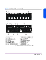
Page 54: ...54 Product Overview Figure 21 VA 7110 I O Architecture ...
Page 90: ...90 Troubleshooting ...
Page 116: ...116 Servicing Upgrading Figure 45 Removing Installing an Array Controller Filler Panel 1 2 3 ...
Page 129: ...Servicing Upgrading 129 Servicing Upgrading Figure 52 Removing and Installing an LCC 1 2 3 ...
Page 130: ...130 Servicing Upgrading Figure 53 Setting the FC Loop Speed Switch Must be set to 1GB s ...
Page 149: ...Specifications Regulatory Statements 149 Specifications Regulatory Statements ...
Page 151: ...Specifications Regulatory Statements 151 Specifications Regulatory Statements ...
Page 152: ...152 Specifications Regulatory Statements ...
Page 164: ...164 Index ...