background image

Figure 35 Removing the bezel cover

4.

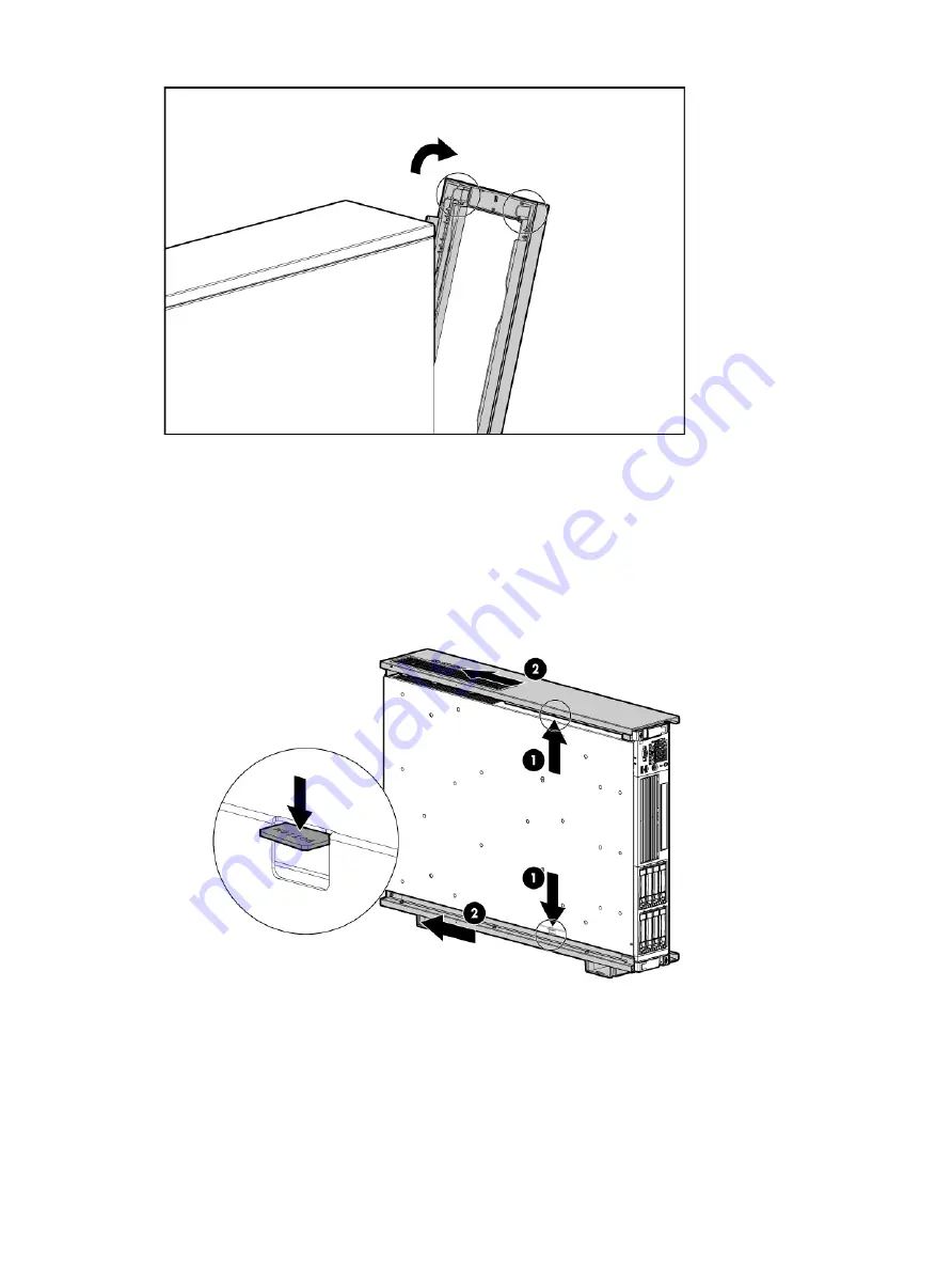
Remove the pedestal top piece.
a.

With the server still in the vertical position, look at the left side of the server (server bottom)
to locate the lock release tab.

b.

Press the lock release tab on the pedestal top piece away from the chassis to unlock the
pedestal top piece from the server. See

Figure 36

for the pedestal top and bottom piece

lock release locations.

Figure 36 Removing the pedestal top piece

c.

Slide the pedestal top piece toward the back of the server to release it from the server.

d.

Once the pedestal component has moved about 1/4 inch, the lock releases, and you
can release the tab.

e.

Pull the pedestal kit top piece away from the server.

f.

Repeat these steps for the bottom piece.

HP Confidential

102 Removal and replacement procedures

Summary of Contents for integrity rx2800 i4

Page 1: ...P product This document provides system information server specifications and installation procedures for the HP Integrity rx2800 i4 Server It also provides information on parts troubleshooting diagnosing server issues and how to remove and replace server components HP Part Number AT101 9014A Published November 2012 Edition 1 HP Confidential ...

Page 2: ...he publishing history table identifies the publication dates of this manual Updates are made to this publication on an unscheduled as needed basis The updates will consist of a complete replacement manual and pertinent online or CD documentation The document printing date and part number indicate the current edition The printing date changes when a new edition is printed Minor changes might be mad...

Page 3: ... 3 Installing the server 18 Safety information 18 Preventing electrostatic discharge 18 Installation sequence and checklist 19 Installing the server into a rack or pedestal 19 Rack installation 19 HP rack 19 Non HP rack 19 Pedestal kit installation 19 Remove the rails from the server 19 Attaching the pedestal kit top and bottom 20 Attaching the bezel cover 22 Attaching the pedestal kit side pieces...

Page 4: ...FI Boot Manager 38 Booting HP UX from the UEFI Shell 38 Booting HP UX in single user mode 38 Booting HP UX in LVM maintenance mode 39 Shutting down HP UX 39 5 Optional components 40 Installing a hot pluggable SAS hard drive 40 Installing a hot swappable power supply 41 Removing the access panel 42 Removing the PCI riser cage 43 Removing expansion slot covers 44 Installing expansion boards 45 Insta...

Page 5: ...roubleshooting methodology 77 Installation troubleshooting using the server power button 77 Server does not power on 77 UEFI menu is not available 78 Operating system does not boot 78 Operating system boots with issues 78 Intermittent server issues 78 SATA DVD RW drive issues 78 SAS disk drive issues 79 Console issues 79 Troubleshooting the processor and memory 79 Troubleshooting the server proces...

Page 6: ...g SAS hard drive 104 Removing and replacing a power supply blank 105 Removing and replacing a hot swap power supply 105 Removing and replacing the access panel 106 Removing and replacing the optical drive filler 107 Removing and replacing the optical drive 107 Removing and replacing a hot swap fan 108 Removing and replacing the power supply backplane 109 Removing and replacing the hard drive backp...

Page 7: ...he Driver ID and CTRL ID 139 Using the ORCA menu driven interface 139 Creating a logical drive 140 Deleting a logical drive 140 Adding a RAID Advanced Pack license key 140 Viewing RAID advanced pack license keys 141 UEFI 141 UEFI shell and HP POSSE commands 142 Drive paths in UEFI 144 Using the boot maintenance manager 145 Boot options 146 Add boot option 146 Delete boot option 147 Change boot ord...

Page 8: ...rd drives Disk drives I O riser options PCI slots One full height full length PCIe x8 and two low profile PCIe x4 slots One full height full length PCIe x8 and one low profile PCIe x8 slots Eight port SAS core I O card or eight port SAS core I O card with internal RAID SAS I O Four GigE LAN ports LAN I O One serial port four USB 2 0 ports one 1G 100 10 LAN port and two VGA ports NOTE The serial po...

Page 9: ...Server subsystems Internal components Figure 1 Internal components 3 2 1 DIMM risers Processors Fans HP Confidential Server subsystems 9 ...

Page 10: ...an 5 connector 13 SAS B connector 4 Processor socket 1 5 SATA optical drive connector 23 Fan 4 connector 14 SAS A connector 15 24 Secondary riser connector Fan 3 connector 6 CPU 0 power connector 25 16 Internal USB connector SAS cache module connector 7 Front I O connector 26 Fan 2 connector 17 SAS power connector 8 Power supply backplane connector 27 Fan 1 connector 18 CPU 1 power connector 9 Int...

Page 11: ...y loaded with x16 connectors The secondary I O riser position can either be a riser that supports one full height full length PCIe x8 and two low profile PCIe x4 add in cards or a riser that supports one full height full length PCIe x8 and one low profile PCIe x8 RAID support The following levels of RAID support are offered Zero memory RAID 0 1 10 Maximum 8 drives 2 logical volumes No cache or sup...

Page 12: ...sks with Zero Memory LUN 1 RAID 1 bays 1 2 LUN 2 RAID 0 bays 3 4 5 6 7 Hot Spare bay 8 LUN 1 RAID 10 bays 1 2 3 4 LUN 2 RAID 10 bays 5 6 7 8 LUN 1 RAID 0 bays 1 2 3 LUN 2 RAID 10 bays 5 6 7 8 Hot Spare bay 4 Controls and ports Front panel controls and ports Figure 4 Front panel components 5 Hard drive bays 1 Quick release levers 2 iLO 3 information pull tab 6 USB connectors 7 3 SID Video connector...

Page 13: ... panel components 17 NIC 2 connector 9 Power supply 2 power connector 1 PCI 5 2 18 PCI 6 iLO 3 physical presence pinhole button 10 Power supply 1 3 PCI 4 19 Serial connector 1 1 Power supply 1 LED 4 PCI 2 20 12 iLO 3 connector Power supply 1 power connector 5 PCI 3 21 NIC 3 connector 6 PCI 1 13 UID LED button 22 NIC 4 connector 7 Power supply 2 14 USB connectors 2 23 NIC link LED 8 Power supply 2 ...

Page 14: ...t is identical in size insulation material and thickness to the branch circuit supply conductors The PE conductor must be green with yellow stripes The earthing conductor is to be connected from the unit to the building installation earth or if supplied by a separately derived system at the supply transformer or motor generator set grounding point Server electrical specifications System power spec...

Page 15: ...to turn off the server power consumption falls below the low power consumption but does not reach zero To reach zero power consumption in off mode disconnect all power supplies from their power sources Power consumption and cooling The power consumptions listed in Table 5 page 15 are valid for the configuration shown Please use the HP Power Advisor tool to obtain power information for other config...

Page 16: ...m 574 ft above 900 m 3000 ft 2 Two eight core processor modules Twenty four DIMMs on four memory risers Eight hard disk drive Six cards on two risers Two power supplies Unpacking and inspecting the server This section describes pre installation procedures Ensure that you have adequately prepared your environment for installing the new server received the components that you ordered and verified th...

Page 17: ...tomer service representative The service representative initiates appropriate action through the transport carrier or the factory and assists you in returning the equipment Unloading the server with a lifter WARNING Use caution when using a lifter Because of the weight of the server to avoid injury you must center the server on the lifter forks before lifting it off the pallet NOTE HP recommends t...

Page 18: ...n power switch is off Failure to observe this warning might result in personal injury or equipment damage Do not wear loose clothing that might snag or catch on the server or on other components Do not wear clothing subject to static charge buildup such as wool or synthetic materials If installing an internal assembly wear an antistatic wrist strap and use a grounding mat such as those included in...

Page 19: ...rack For more information on rack deployment stabilization and transportation see the 10000 Series G2 Rack Best Practices Guide http www hp com go rackandpower Non HP rack For information on installing a rx2800 i4 server in a third party rack see the QuickSpecs located on the HP Integrity rx2800 i4 Server product page at http h18000 www1 hp com products quickspecs 14464_div 14464_div HTML To view ...

Page 20: ...T In this document the server top bottom right and left refer to the server as faced from the front with the server in a horizontal orientation The pedestal kit components are referred to by the final position with the server in a vertical orientation For example the pedestal kit bottom attaches to the server right side HP Confidential 20 Installing the server ...

Page 21: ...n the server so try to position the server so the right side in the horizontal position of the server hangs off the edge of the work surface by a few inches to allow the bottom piece to be attached to the server chassis If that is not possible then raise up the server approximately three inches from the work surface to enable the pedestal kit bottom piece to be attached to the server right side To...

Page 22: ...the server NOTE One of the holes in the pedestal component contains the locking mechanism This makes the hole appear partially blocked 6 Hold the pedestal top piece flush against the server 7 Slide the pedestal top piece forward until it locks into place 8 The top and bottom pedestal kit pieces are now in place Attaching the bezel cover To attach the bezel cover 1 Apply the rx2800 i4 product label...

Page 23: ...l kit right side piece WARNING The ventilation holes in the pedestal kit right side piece must be matched up with the ventilation holes on the top cover of the HP Integrity rx2800 i4 Server to enable proper cooling and air flow Failure to heed this warning causes the server to shut down with an overtemp condition To attach the component 1 Align the posts on the pedestal kit right side piece with t...

Page 24: ... 1 Attaching the pedestal kit side piece 3 Secure the pedestal side by hand tightening the captive thumb screws on the rear of the server Figure 12 Thumb screw locations HP Confidential 24 Installing the server ...

Page 25: ... two power supplies can be installed in the server Installing two power supplies in the server provides 1 1 redundancy meaning that if one power supply fails there is still enough power supplied to the server to operate You must promptly replace the failed power supply to restore 1 1 functionality All high line 220 V configurations are capable of 1 1 redundancy Low line 1 10 V configurations can m...

Page 26: ...00 i4 Server User Service Guide shows the ports and power supplies located on the rear panel of the server Applying standby power to the server 1 Plug the power cord into the receptacle in power supply 2 Plug the other end of the power cord into an AC outlet NOTE The LED on the power supply does not illuminate in the standby power state The LED is green when the server is powered on to full power ...

Page 27: ...ace between the server OS and the server firmware UEFI provides a standard environment for booting an OS and running preboot applications Use this procedure to access UEFI or the OS from the iLO MP Your security parameters were set regarding remote access NOTE Commands are case insensitive 1 From the MP Main Menu enter the commandco to access the Console NOTE Terminal windows must be set to a wind...

Page 28: ... OS is installed at the time of purchase you are taken to UEFI shell prompt OS login prompt If the server has a factory installed OS you can interrupt the boot process to configure your specific UEFI parameters If you are at the UEFI shell prompt go to UEFI Front Page page 28 If you are at the OS login prompt go to OS login prompt page 31 UEFI Front Page If you are at the UEFI shell prompt enter t...

Page 29: ... boot option press B to launch the Boot Manager Figure 16 Boot Manager screen To configure specific devices press D to launch the Device Manager This is an advanced feature and must only be performed when directed HP Confidential Accessing UEFI or the OS from iLO MP 29 ...

Page 30: ...Tool Saving UEFI configuration settings You can configure other UEFI settings at this time For more UEFI configuration options see the HP Integrity rx2800 i4 Server User Service Guide Booting and installing the operating system From the UEFI Front Page prompt you can boot and install in either of two manners If your OS is loaded onto your server see Operating system is loaded onto the server page ...

Page 31: ... Full power Off For details about server power states see Table 7 page 26 NOTE If the power restore feature is set to Always On through the iLO 3 MP PR command the server automatically powers on to the full power state when the power cord is plugged in to the server Powering on the server Power on the server to full power using the following methods if the server is in the standby power state iLO ...

Page 32: ...e operating system documentation Powering off the server If the server is in the standby or full power state power off the server by using either of the following methods iLO 3 MP PC command Power button Powering off the server using the iLO 3 MP 1 Gracefully shut down the operating system See the operating system documentation for more information 2 Initiate a console session and access the MP Ma...

Page 33: ...tes are handled in a manner that reduces any downtime required for the update process HP Smart Update Manager does not require an agent for remote installations After the installation is complete HP Smart Update Manager also removes all remote files associated with the installation Key features of HP Smart Update Manager are GUI and CLI Dependency checking which ensures appropriate installation or...

Page 34: ... later 1 Insert the OS Media into the DVD internal to system or tape drive external to system 2 Power on the server and boot to UEFI If the server is already powered on then using the reset command at the UEFI prompt reboot to UEFI 3 From the UEFI Front Page press S to launch the UEFI Shell NOTE If the device is already selected or you already know the device name skip the following step If you ar...

Page 35: ...07F6FFC 0x0 0x1 NoTopology 0 0 0 0x0 Select Desired Tape 01 input 01 If the correct media is installed it will boot from tape when you enter the index number If there is no media in the SAS tape drive and you select 1 you will see the following message tapeboot Could not load tapeboot image The operating system will start loading onto the server 5 Follow the on screen instructions to install the O...

Page 36: ... UEFI Front Page menu With autoboot enabled UEFI loads the first item in the boot options list after a designated timeout period Configure the autoboot setting for an HP Integrity server using either the UEFI Shell autoboot command or the Set Time Out Value menu item from the Boot Maintenance Manager Examples of autoboot commands for HP UX Disable autoboot from the UEFI Shell by issuing autoboot o...

Page 37: ...number 2 enter fs2 The UEFI Shell prompt changes to reflect the file system currently accessed The full path for the HP UX loader is EFI HPUX HPUX EFI and is on the device you are accessing 3 At the UEFI Shell environment use the bcfg command to manage the boot options list The bcfg command includes the following options for managing the boot options list bcfg boot dump Display all items in the bo...

Page 38: ...at is mapped as fs0 at the UEFI Shell prompt enter fs0 5 To launch the HPUX EFI loader from the currently selected boot device at the UEFI Shell command prompt enter HPUX If needed specify the full path of loader by entering EFI HPUX HPUX at the UEFI Shell command prompt 6 Allow the HPUX EFI loader to proceed with the boot command specified in the AUTO file or manually specify the boot command By ...

Page 39: ...the Console menu to access the system console Accessing the console through iLO MP enables you to maintain console access to the server after HP UX has shut down 2 Use the shutdown command with the appropriate command line options The command line options you specify determines the way in which HP UX shuts down and whether the server is rebooted Choose an HP UX shutdown option for your server To s...

Page 40: ...appable or hot pluggable component Voltage is present at various locations within the server whenever an AC power source is connected This voltage is present even when the main power switch is turned off Failure to observe this warning can result in personal injury or damage to the equipment Installing a hot pluggable SAS hard drive The front of the server has eight hot plug SAS hard drive slots S...

Page 41: ...1 Power supply bay 2 CAUTION Observe all ESD safety precautions before attempting this procedure Failure to follow ESD safety precautions might result in damage to the server CAUTION If you do not purchase a second power supply the empty power supply slot must remain covered with the supplied power supply blank Failure to observe this caution might result in server shutdown due to overheating NOTE...

Page 42: ... supply blank 2 Install the power supply Removing the access panel 1 Use the T 15 Torx screwdriver attached to the rear of the server to loosen the security screw on the hood latch HP Confidential 42 Optional components ...

Page 43: ...led If the server supports hot pluggable components minimize the amount of time the access panel is open 1 Disconnect any cables connected to optional I O cards before removing cage 2 Remove the PCI riser cage To replace the component reverse the removal procedure When replacing the PCI riser cage to ensure that it has properly seated into the system board push down on the top of the component whe...

Page 44: ...s hot plug components minimize the amount of time the access panel is open 1 Remove the access panel Removing the access panel page 42 2 Remove the PCI riser cage Removing the PCI riser cage page 43 3 Remove the expansion slot cover To remove slot cover 1 or 4 push the retainer to release it and then slide out the cover To remove slot covers 2 and 3 lift up and remove the latch and then remove the...

Page 45: ...ve the access panel See Removing the access panel page 42 2 Remove the PCI riser cage See Removing the PCI riser cage page 43 3 Remove the expansion slot cover See Removing expansion slot covers page 44 4 Install the expansion board 5 Connect any required internal cables to the expansion board 6 Reinsert the PCI riser cage into the chassis 7 Connect any required external cables to the expansion bo...

Page 46: ...I O card cage The DIMMs are partitioned by the number of processors installed in the server If you have only one processor installed in the system you can only use 12 of the 24 memory slots CAUTION Observe all ESD safety precautions before attempting this procedure Failure to follow ESD safety precautions might result in damage to the server Memory riser locations and slot IDs Install DIMMs into t...

Page 47: ... 3 6 1B and 6B Memory riser 2 7 1B and 6B Memory riser 4 8 2C and 5C Memory riser 1 9 2C and 5C Memory riser 3 10 2C and 5C Memory riser 2 1 1 2C and 5C Memory riser 4 12 IMPORTANT A maximum of 8 DIMMs are supported in a configuration with low line AC voltage and 2 processors TIP You can load DIMM pairs on a single riser at a time but this option reduces system performance Supported DIMM sizes DIM...

Page 48: ...loaded in an economic order for example loading the first riser full before loading DIMMs on other memory risers but the DIMMs must still follow the basic DIMM load sequence Load highest density DIMMs first Load DIMMs in pairs by increasing letter Mixed DIMM types are supported with the following qualifications DIMMs with x4 and x8 modes can be mixed DIMMs with different sizes can be mixed DIMMs w...

Page 49: ...3 Install the DIMM HP Confidential Installing DIMMs 49 ...

Page 50: ... the second processor in socket 1 CAUTION Processor speed number of cores and cache size must be identical for all the processors installed in a server To ensure compatibility whether upgrading replacing or adding an additional processor use processors with identical part numbers Failure to observe this caution results in performance degradation or server failure CAUTION Observe all ESD safety pre...

Page 51: ...e to the processor handle the processor only by the edges Do not touch the bottom of the processor especially the contact area CAUTION To prevent possible server malfunction and damage to the equipment multiprocessor configurations must contain processors with the same part number CAUTION To prevent thermal instability and damage to the server do not separate the processor from the heat sink after...

Page 52: ...essor module b Place the label on the top of the heat sink 3 Remove the processor airflow baffle 4 Install the processor over the load posts NOTE Ensure pin 1 indicated on the empty socket with an embossed triangle matches the pin 1 marker on the processor module the chamfered corner of its attached voltage regulator heat sink 5 Remove the heat sink cover HP Confidential 52 Optional components ...

Page 53: ... server and processor ensure the processor heat sink locking handle is fully back against the stops rotated approximately 120 back Also verify that the plastic tabs on the processor heat sink are fully pulled out before installation 6 Install the heat sink over the load posts CAUTION Do not lower the heat sink locking handle before pushing the plastic locking tabs into place HP Confidential Instal...

Page 54: ...parate the processor module from the processor heat sink after they have been coupled NOTE Positive engagement clicking must occur during engaging of the processor heat sink and processor module onto the socket to ensure proper seating HP Confidential 54 Optional components ...

Page 55: ...e following figure WARNING The heat sink locking lever can constitute a pinch hazard Keep your hands on top of the lever during installation to avoid personal injury CAUTION To prevent thermal instability and damage to the server do not separate the processor module from the processor heat sink after they have been coupled HP Confidential Installing a processor 55 ...

Page 56: ...fails the system board needs to be replaced by an HP authorized service provider Attempting to remove the TPM from the system board will void any existing HP service contract and cause the server to fail CAUTION Any attempt to remove an installed TPM from the system board breaks or disfigures the TPM security rivet Upon locating a broken or disfigured rivet on an installed TPM administrators shoul...

Page 57: ...pears NOTE Your display might not match the display shown info all SYSTEM INFORMATION Details omitted CPU INFORMATION Details omitted BOOT PROCESSOR INFORMATION Details omitted MEMORY INFORMATION Details omitted I O INFORMATION Details omitted PCI DEVICE INFORMATION Details omitted CONSOLE CONFIGURATION Details omitted BOOT INFORMATION Details omitted FIRMWARE INFORMATION Details omitted SYSTEM SE...

Page 58: ...components are installed 1 Close the processor cage 2 Install the PCI riser cage 3 Install the access panel 4 Install the server into the rack or pedestal 5 Connect all cables 6 Power on the server HP Confidential 58 Optional components ...

Page 59: ...d issue to the specific troubleshooting procedure required Isolate the failure to a specific part of the server so you can perform more detailed troubleshooting For example Issue Front panel LED blinking NOTE The front panel health LEDs flash amber with a warning indication or flash red with a fault indication System Alert on console Analyze the alert by using the system event log SEL and forward ...

Page 60: ...iLO 3 MP vfp command 3 Compare the state of the server LEDs off flashing or steady red green or amber with the LED states listed in the LED Panel State Table in this section 4 Go to the step number of the Basic Low End Troubleshooting Table as specified in the right column of the LED Panel State Table located in the row which corresponds to your front panel LED display state 5 Read the symptom con...

Page 61: ...s are on and no fans are running 1 2 Verify that the power cords are connected to both the power supplies and to the AC receptacles 3 Verify that AC power at the proper AC voltage levels is available to the receptacles 4 Check the front panel connector and the cable to the rest of the system 5 If the integrated power button LED on front panel remains off then re seat the power supplies replace the...

Page 62: ... and power is steady green Nothing might be logged for this condition 1 The most common reasons for this are local console device cabling issues local console device configuration issues etc Check these issues first 2 Be sure that that the RS 232 configuration matches between the server and the local console see Troubleshooting the system console page 90 for more details 3 Reset iLO 3 MP by using ...

Page 63: ...gs for entries related to processors processor power modules PPMs shared memory and core I O devices see Errors and reading error logs page 73 for more details The preceding issue is fixed when all boot devices are found Nothing is logged for this condition system health is off or steady green and power is steady green There are RAID channel redundancy failures 4d Examine the LED next to each RAID...

Page 64: ...er from through OS recovery routines system health is flashing red SEL is red and power is steady green 1 Capture the MCA dump with the UEFI errdump mca command If the system can boot the OS you can capture binary MCA dump files online MCA occurs during server operation the server reboots the OS NOTE Server reboots OS if enabled 8a 2 Examine the iLO 3 MP logs for entries related to processors proc...

Page 65: ...fatal fault has occurred system is on or in standby mode Flashing Red A fatal fault has been detected and a FRU or subsystem has failed View the SID other LEDs and the logs for information Off Health good on all internal FRUs and system off NOTE The System Health LED does not change status if AC power is removed from a single power supply in a system with power redundancy This button manually powe...

Page 66: ...ible entities are repaired and report that they are good or on any AC or standby power cycle The iLO 3 MP displays the following strings in its Virtual Front Panel for the three states of this LED Table 16 VFP health description VFP Status LED Status none Off External parts including fans and power supplies okay On green A redundant externally accessible CRU failed check SID LEDs Flashing red Loca...

Page 67: ...t Log Green Normal Red System fatal Component LEDs Off Component health is assumed good Amber Component health last known to be bad NOTE The Power Supply LED is lit only when a failure or fault is detected in a power supply Loss of AC power to a power supply generates a SEL entry but does not result in the Power Supply LED becoming lit The System Insight Display improves serviceability by enabling...

Page 68: ...system is up or down the health LED does not tell the user if the system is booted To cover the wide range of faults for which software firmware is not 100 sure that a CRU must be re seated replaced The system health LED does not illuminate unless software firmware can make a solid determination that a CRU must be re seated replaced This LED indicates the overall health state of the system includi...

Page 69: ...larly flashing amber 1 Hz On The drive is online but it is not active currently Off On CAUTION Do not remove the drive Removing a drive might terminate the current operation and cause data loss Regularly flashing amber 1 Hz Flashing regularly 1 Hz The drive is part of an array that is undergoing capacity expansion or stripe migration but a predictive failure alert has been received for this drive ...

Page 70: ...O 3 link LED 2 UID LED button 4 NIC iLO 3 activity LED Table 22 Rear panel LEDs and buttons Status Name Power supply LED Green Normal Off System is off or power supply has failed UID LED button Blue Identification Flashing blue Remote iLO session or a firmware flash update is in progress Off Off NIC iLO 3 activity LED Green Network activity Flashing green Network activity Off No network activity N...

Page 71: ...ve full power plug the power cord into the appropriate receptacle and either push the power button or enter the iLO 3 MP PC command In the off state the power cords are not connected to a power source Table 23 Power supply LED states Indication LED state No AC power Off Full power on normal operation Green Diagnostics A suite of offline and online support tools are available to enable manufacturin...

Page 72: ...y are intended to be interactive and rely on users to provide information necessary to perform a particular task These tools require users to have the appropriate license if they wish to run them Online support tool availability Online diagnostics are included in the HP UX OE media and are installed by default Online support tools list The following online support tools are available on HP UX 1 1 ...

Page 73: ...ultMgmt WBEM indication providers WBEM provides frameworks for monitoring and reporting events SysFaultMgmt WBEM indication providers enable users to monitor the operation of a wide variety of hardware products and alert them immediately if any failure or other unusual event occurs By using hardware event monitoring users can virtually eliminate undetected hardware failures that could interrupt sy...

Page 74: ...he event logs 1 Connect to the system console 2 Use Ctrl B to access the iLO 3 MP menu 3 Use the sl command to view event logs System Event E and Forward Progress F logs are very useful in determining the context of an error see the following figure for an example NOTE Remember that E shows only event logs for Warning Critical or Fatal faults by default F shows all event log outputs System Event L...

Page 75: ... the console execute the MP DF command The following CRU IDs appear Your display might not exactly match the display shown FRU IDs 00 System Board 02 Display Board 04 Power Supply 1 42 Virtual Connect NOTE Your display might not exactly match the display shown 5 Remove the AC power Add CPU 0 memory expansion board 1 2 DIMMs 4A and 3A slots Plug in AC power and check to ensure the CPU memory riser ...

Page 76: ... after CPU memory expansion and DIMMs change then you must replace the system board With a good CPU memory expansion and DIMMs your system will boot to UEFI and will display the following event text messages NOTE Your display might not exactly match the display shown FRU IDs Log Entry 11 03 Aug 2012 11 04 58 Alert Level 2 Informational Keyword EFI_START CPU starting to boot EFI Logged by System Fi...

Page 77: ... server power button The server power button on the front panel operates differently depending on how long the button is pressed and on what the system is doing when the button is pressed You must be aware of the uses to properly troubleshoot the system Table 26 Server power button functions when server is on and at UEFI Reaction Action System power turns off immediately hard power off 1 3 seconds...

Page 78: ...se the following tools to view the system logs Analyze any error messages to resolve the issue UEFI Shell iLO 3 Operating system boots with issues If the operating system is running and you are experiencing issues use the following tools to resolve the issue LEDs Error Messages and event logs Intermittent server issues You can usually trace intermittent issues that occur during installation to pow...

Page 79: ...nd physical memory ranks Troubleshooting the server processor The server supports both quad core and octo core processors Each server supports one or two processor modules The quad core processor module contains four individual processor cores When two quad core processors are installed in the server the server contains eight physical processors Similarly the octo core processor module contain eig...

Page 80: ...iagnostic LEDs This event follows other SFW Processor failed and deconfigured Type E0h 39d 04d BOOT_DECONFIG_CPU Processors failed processors Threshold exceeded for WIN Agent Too many cache errors Type E0h 5823d 26d PFM_CACHE_ERR_PROC Processors cache parity detected by processor errors on processor Threshold exceeded for WIN Agent Too many corrected Type E0h 5824d 26d PFM_CORR_ERROR_MEM Processor...

Page 81: ... Type E0h 83d 26d BOOT_RENDEZ_FAILURE Processors thread rendezvous failure SFW The logical monarch Type E0h 67d 26d BOOT_MONARCH_TIMEOUT Processors processor thread has timed out SFW A logical slave processor Type E0h 57d 26d BOOT_INCOMPATIBLE_SLAVE Processors thread is incompatible with logical monarch processor SFW Processor PAL incompatible with processor Type E0h 56d 26d BOOT_INCOMPATIBLE_ PAL...

Page 82: ...Display is not lit For configuration type errors for example if DIMMs are not installed the CRU LEDs on the SID LED panel illuminate for the missing DIMMs No diagnostic messages are reported for single byte errors that are corrected in both ICH10 caches and DIMMs during CPE events Diagnostic messages are reported for CPE events when thresholds are exceeded for both single byte and double byte erro...

Page 83: ...ED does not change status if AC power is removed from a single power supply in a system with power redundancy Power subsystem behavior For the server each bulk power supply CRU provides 800 watts of DC power from a nominal 120 VAC 50 60 Hz and 1200 watts from a nominal 240 VAC 50 60 Hz The iLO MP chip located on the system board controls the flow of 12 V DC power to the server CRUs You can control...

Page 84: ...ooting the cooling subsystem The fans located within the server provide N 1 redundancy for the server using six identical dual fan assembly CRUs In turn each dual fan assembly CRU provides additional N 1 redundancy for the fan cooling zone it controls Each dual fan assembly CRU is identified by the server as fans 1 through 6 both for logging purposes and for fault identification on the diagnostic ...

Page 85: ...Direct Memory Access DMA and is initiated by I O devices located in I O or on Host Bus Adapter HBA I O cards and does not involve any logical processors In addition system firmware performs the following tasks to configure the I O subsystem 1 Sets up the PCIe Root Complex Initialize and configure all root ports Initialize and configure all I O devices including memory space and I O port space allo...

Page 86: ..._RECOVERABLE I O Riser range likely too low A voltage on the disk backplane is iLO MP Voltage on CRU is inadequate Type 02h 02h 07h 03h VOLTAGE_DEGRADES_TO_NON_RECOVERABLE Disk Backplane out of range likely too low Table 37 I O card events that might illuminate SID LEDs Notes Source Cause Sample IPMI Events Diagnostic LEDs Disallow O S boot and display SFW A non hot plug I O slot power consumption...

Page 87: ...O Card SFW I O host bridge Lower Bus Adapter is Type E0h 136d 26d IO_LBA_RESET_ERROR I O Card inaccessible because rope reset failed to complete SFW PCI clock DLL error Type E0h 130d 26d I O Card IO_DLL_ERROR SFW I O rope reset failed to complete Type E0h 143d 26d IO_ROPE_RESET_ERROR I O Card SFW PCIe link failed to train Type E0h 7346d I O Card CC_IODISC_LBA_LINK_TRAIN_ERR SFW PCIe link is not ru...

Page 88: ...dy amber Off Off 2 System power rails are on when power switch is toggled Off Steady green Off Off 3 System power rails are on iLO MP drives system health LED Off Steady green Steady green Off 4 System is booting firmware has passed BOOT_START in firmware Off Steady green Steady green Off 5 System has finished booting firmware and an OS is either booting or running Off Steady green Steady green St...

Page 89: ...re SAS HDD firmware LOM firmware System firmware and iLO 3 firmware must be from the same release Independent updates are not supported Details about a specific release are available in the associated Release Notes Firmware updates are available from the HP website at http www hp com under Support and Drivers Identifying and troubleshooting firmware issues Erratic system operation or the fact that...

Page 90: ...nd at the UEFI shell prompt to determine the current system firmware version Figure 26 sr command at the command menu Figure 27 info fw command at the shell prompt 3 Choose the appropriate firmware package from the choices available on the HP Support Center web page at http www hp com go bizsupport To verify the firmware version see the Release Notes or Installation Instructions To update firmware...

Page 91: ...r environment Ambient intake air temperature is often different from ambient room temperature Measure the operating temperature and humidity directly in front of the cabinet cooling air intakes rather than measuring ambient room conditions only Within the server temperature sensors report server temperature to the iLO which controls fan speed based on this information Temperature sensors are found...

Page 92: ...10600R 512Mx4 RoHS 708394 001 DIMM 8GB PC3L 10600R 512Mx4 RoHS 708395 001 DIMM 16GB PC3L 10600R 1Gx4 RoHS Power supply 660185 001 SPS POWER SUPPLY 1200W 1U HEPB Internal disks and removable media 512743 001 SPS DRV HD 72G SAS 2 5DP 15K 6 507283 001 SPS DRV HD 146GB 10K 2 5 DP H 512744 001 SPS DRV HD 146G SAS 2 5DP 15K 507284 001 SPS DRV HD 450GB 10K 2 5 6G SAS HP 581310 001 SPS DRV HD 450GB 10K 2 ...

Page 93: ...PL HP PCIe 1p 4GB FC 1P 100 AD222 67102 SPS PCA I O PCIe 2p 4Gb FC 2p 1000BT AD393 67001 RPL HP PCIe 2p 4GB FC 2P 1000SX Adptr 489190 001 HP AH400A 1 port 8 Gb PCIe FC SR QLogic HBA 489191 001 HP AH401A 2 port 8 Gb PCIe FC SR QLogic HBA 489192 001 PCIe single port Fiber Channel FC 81e Host Bus Adapter HBA board 489193 001 SPS BD HBA 82e DP FC PCIe AH423 67001 SPS BD PCA PCIe 2D FireMV2250 Graphics...

Page 94: ...ccessible at all times Unplug the power cord from the power supply to disconnect power to the equipment Do not route the power cord where it can be walked on or pinched by items placed against it Pay particular attention to the plug electrical outlet and the point where the cord extends from the server WARNING To reduce the risk of personal injury from hot surfaces allow the drives and the interna...

Page 95: ...from the rack Removing the server from the rack page 99 If the rack environment cabling configuration or the server location in the rack creates awkward conditions remove the server from the rack Extending the server from the rack 1 Pull down the quick release levers on each side of the server 2 Extend the server from the rack WARNING To reduce the risk of personal injury or equipment damage be su...

Page 96: ...RNING To reduce the risk of personal injury be careful when pressing the server rail release latches and sliding the server into the rack The sliding rails might pinch your fingers Accessing internal components for a pedestal mounted server 1 Power off the server and remove all cables 2 Remove the pedestal kit feet HP Confidential 96 Removal and replacement procedures ...

Page 97: ...he left side facing the front of the server The right side of the pedestal kit with the ventilation holes must face up 4 Unscrew the captive thumbscrews on the rear of the pedestal kit for the right side pedestal kit piece HP Confidential Preparation procedures 97 ...

Page 98: ...ocations 5 To remove the pedestal kit piece from the pedestal slide the right side piece toward the back of the server and then lift it Figure 30 Removing the side piece HP Confidential 98 Removal and replacement procedures ...

Page 99: ... 3 Press the Power On Standby button to place the server in Standby mode When the server activates Standby power mode the system power LED changes to amber NOTE Pressing the UID button illuminates the blue UID LEDs on the front and rear panels In a rack environment this feature facilitates locating a server when moving between the front and rear of the rack 4 Disconnect the power cords The system ...

Page 100: ... in the server service guide 2 Disconnect the power and LAN cables connected to the server Removing the pedestal kit 1 Remove pedestal feet Figure 32 Removing the pedestal kit feet 2 Remove the pedestal side pieces by unscrewing the captive thumbscrews on the rear of the pedestal kit and sliding the side pedestal kit pieces toward the back of the server HP Confidential 100 Removal and replacement ...

Page 101: ...Figure 33 Thumbscrew locations Figure 34 Removing the side piece 3 Release the locking tabs behind the top corners of the bezel cover and remove the component HP Confidential Preparation procedures 101 ...

Page 102: ...estal top piece from the server See Figure 36 for the pedestal top and bottom piece lock release locations Figure 36 Removing the pedestal top piece c Slide the pedestal top piece toward the back of the server to release it from the server d Once the pedestal component has moved about 1 4 inch the lock releases and you can release the tab e Pull the pedestal kit top piece away from the server f Re...

Page 103: ...arm with right hand swing NOTE To access some components you might have to remove the cable management arm To access the product rear panel components open the cable management arm 1 Power off the server Powering off the server page 99 2 Swing open the cable management arm 3 Remove the cables from the cable trough HP Confidential Preparation procedures 103 ...

Page 104: ...s into place Removing and replacing a hot plug SAS hard drive The server supports up to eight SFF 2 5 inch SAS hard drives Each drive is equipped with two LEDs that indicate activity and device status To remove the component CAUTION For proper cooling do not operate the server without the access panel baffles expansion slot covers or blanks installed If the server supports hot plug components mini...

Page 105: ...e removal procedure Removing and replacing a hot swap power supply The server supports 1 1 redundant power supply for high line 1200W 200 240VAC and low line 800W 100 120VAC in the data center and office friendly server versions Table 42 Power redundancy configurations Redundancy DIMM count Processor count Power supply count Line voltage No 2 to 24 1 or 2 1 High Line 200 240 Yes 2 to 24 1 or 2 2 H...

Page 106: ... unless all bays are populated with either a component or a blank To remove the component 1 Determine how many hot swap power supplies are installed If only one hot swap power supply is installed power off and remove the power cord from the server Powering off the server page 99 If more than one hot swap power supply is installed continue with the next step 2 Access the product rear panel Accessin...

Page 107: ...h of at least 20 cm and a thickness of about 1 mm to push out the drive filler HP recommends using a ruler or similar tool To replace the component reverse the removal procedure Removing and replacing the optical drive CAUTION To prevent improper cooling and thermal damage do not operate the server unless all bays are populated with either a component or a blank 1 Power off the server Powering off...

Page 108: ...he fans are all redundant hot swappable and interchangeable If one fan unit fails then the other fans increase speed to compensate The fan units are N 1 redundant meaning that the server has six fan units but can operate with five fan units running CAUTION If more than one fan is removed or fails the system does not shut down If the temperature sensors detect conditions outside of operating limits...

Page 109: ...l page 106 3 Remove the fan CAUTION Do not operate the server for long periods with the access panel open or removed Operating the server in this manner results in improper airflow and improper cooling that can lead to thermal damage To replace the component reverse the removal procedure Removing and replacing the power supply backplane 1 Power off the server Powering off the server page 99 2 Remo...

Page 110: ... replace the component reverse the removal procedure Removing and replacing the hard drive backplane 1 Power off the server Powering off the server page 99 2 Extend or remove the server from the rack Removing the server from the rack page 99 or Extending the server from the rack page 95 3 Remove the access panel Removing the access panel page 42 4 Remove all hot plug hard drives Removing and repla...

Page 111: ...he PCI riser cage page 43 To replace the component reverse the removal procedure Removing and replacing expansion slot covers To remove the component see Removing expansion slot covers page 44 To replace the component reverse the removal procedure Removing and replacing expansion boards Table 43 PCI slot descriptions 2 slot PCIe riser 3 slot PCIe riser Primary riser connector PCIe2 x16 8 4 2 1 PCI...

Page 112: ...e x4 slots The optional riser board configuration contains one riser board with one full length full height PCIe x8 slot and two half length full height PCIe x4 slots The second board contains one full length full height PCIe x16 slot Removing and replacing a half length expansion board 1 Power off the server Powering off the server page 99 2 Extend the server from the rack Extending the server fr...

Page 113: ... page 95 3 Remove the access panel Removing and replacing the access panel page 106 4 Disconnect any external cables that are connected to the expansion board 5 Remove the PCI riser cage Removing and replacing the PCI riser cage page 111 6 Disconnect any internal cables that are connected to the expansion board 7 Remove the expansion board To replace the component see Installing expansion boards p...

Page 114: ...d Pack license key page 140 1 Power off the server Powering off the server page 99 2 Extend or remove the server from the rack Removing the server from the rack page 99 or Extending the server from the rack page 95 3 Remove the access panel Removing and replacing the access panel page 106 4 Remove the PCI riser cage Removing and replacing the PCI riser cage page 111 5 Disconnect the cable to the s...

Page 115: ...emove the server from the rack Removing the server from the rack page 99 or Extending the server from the rack page 95 3 Remove the access panel Removing and replacing the access panel page 106 4 Remove the PCI riser cage Removing and replacing the PCI riser cage page 111 5 Pull up the latch and push the super capacitor pack to the rear of the server 6 Disconnect the super capacitor pack cable fro...

Page 116: ...em cooling CAUTION Immediately install a processor baffle in an empty processor socket To avoid damage to the socket pins the socket must never be uncovered for more than 5 seconds If the socket is damaged the entire system board must be replaced 1 Power off the server and remove it from the rack Powering off the server page 99 and Removing the server from the rack page 99 2 Remove the access pane...

Page 117: ...ore touching them CAUTION To prevent possible server malfunction do not mix processors of different speeds or cache sizes CAUTION Removing a processor will cause the DIMM loading rules to change See Memory configurations page 46 and use the loading rules for two processors If you do not perform these procedures then any memory associated with the removed processor will not be seen by the system CA...

Page 118: ...2 below WARNING The heat sink locking lever can constitute a pinch hazard keep your hands on top of the lever during installation to avoid personal injury 6 Pull both plastic tabs out see 3 below 7 Lift the processor and heat sink off of the socket pulling straight up HP Confidential 1 18 Removal and replacement procedures ...

Page 119: ...stalling a processor and heat sink module page 51 IMPORTANT DO NOT SEPARATE THE PROCESSOR FROM THE HEAT SINK FOR A DEFECTIVE MATERIAL RETURN The heat sink and processor must be returned as a unit to facilitate testing and root cause analysis Do not discard your heat sink packaging or processor ESD bag Reuse this packaging to return any exchange material You MUST use a new heat sink with an undistu...

Page 120: ... the following DIMM sizes 4 GB 8 GB 16 GB IMPORTANT At this time the rx2800 i4 system supports only 1 35 V DIMMs For memory configurations see Installing DIMMs page 46 1 Power off the server Powering off the server page 99 2 Extend or remove the server from the rack Removing the server from the rack page 99 or Extending the server from the rack page 95 3 Remove the access panel Removing the access...

Page 121: ... memory configuration information see Memory configurations page 46 CAUTION Before inserting the memory riser the three stand off posts on the riser must be aligned with the alignment slots on the system board Failure to align the stand off posts correctly might result in damage to the riser HP Confidential Removing and replacing DIMMs 121 ...

Page 122: ...panel Removing and replacing the access panel page 106 4 Remove the PCI riser cage Removing and replacing the PCI riser cage page 111 CAUTION Do not attempt to remove the battery by hand Doing so can cause the battery holder to separate from the system board CAUTION Do not attempt to remove the battery from the side marked first If your battery holder does not have the marking the side of the hold...

Page 123: ...lay module halfway out of the server 8 Disconnect the Systems Insight Display cable 9 Remove the Systems Insight Display module To replace the component reverse the removal procedure If installing a replacement SID module 1 Retain the SID bezel the transparent light pipe and the black rubber light pipe 2 Install the transparent plastic light pipe onto the SID bezel 3 Install the SID bezel onto the...

Page 124: ...ight pipe onto the plastic light pipe 5 Install the SID board by securing it with the two screws 6 Fasten the two hexagon screws on the front of SID bezel to the VGA port HP Confidential 124 Removal and replacement procedures ...

Page 125: ...er off the server Powering off the server page 99 2 Remove the access panel Removing and replacing the access panel page 106 3 Remove the PCI riser cage Removing and replacing the PCI riser cage page 111 4 Open the processor cage 5 Using a screwdriver remove the switch HP Confidential Removing and replacing the intrusion switch cable 125 ...

Page 126: ...alled on your system board it cannot be removed If the TPM fails the system board needs to be replaced Attempting to remove the TPM from the system board will void any existing HP service contract and cause the server to fail 1 Power off the server Powering off the server page 99 2 Remove all power supplies Removing and replacing a hot swap power supply page 105 3 Remove all hot plug hard drives R...

Page 127: ...Removing and replacing a processor and heat sink module page 117 IMPORTANT Place processor pin covers over the sockets to protect the pins 10 Remove the intrusion switch cable Removing and replacing the intrusion switch cable page 125 1 1 Disconnect all cables connected to the system board 12 Remove the hot swap fans from the fan cage Removing and replacing a hot swap fan page 108 13 Remove the fa...

Page 128: ...ge 109 17 Remove hex screws from the rear video connector and serial connector 18 Remove the rear retaining screw 19 Loosen the two system board thumbscrews 20 Remove the system board from the chassis by pushing it toward the front and then lifting it 21 Remove four screws on the power supply cage and remove power supply cage HP Confidential 128 Removal and replacement procedures ...

Page 129: ...22 Loosen the screws of the processor cage and remove the processor cage 23 Remove the two memory riser assemblies HP Confidential Removing and replacing the system board 129 ...

Page 130: ...processor socket are very fragile Any damage to them may require replacing the system board 3 Install the processors and heat sink or processor heat sink module on the system board Installing a processor page 50 4 Install all components removed from the failed system board CAUTION Do not replace hot plug hard drives until you have configured the RAID controller as detailed below 5 Install the acce...

Page 131: ...S mode to RAID 4 Enter saupdate efi get_mode 0 1 0 0 to verify the SAS mode is set to RAID After you replace the system board you must port over the server serial number product number and UUID Labels on the server indicate these numbers 1 Log in to ILO 3 MP by using SSH for example 2 Access the MP Main Menu NOTE Use ctrl B at any time to return to the main menu 3 Enter CM at the hpiLO prompt A CM...

Page 132: ... your server for example rx2800 i4 The product number of your server which is on the identification label at the front of the unit The serial number of your server which is on the identification label Add on boards or additional hardware installed in the server 2 Be familiar with your system configuration Are you using the LAN RS 232 or web interface to monitor the server How many processors DIMMs...

Page 133: ...y phone go to the HP Support Center HPSC at http www hp com go hpsc Local phone numbers are listed in your native language for help Subscription service HP recommends that you register your product at the Subscriber s Choice for Business website http www hp com country us en contact_us html After registering you will receive email notification of product enhancements new driver versions firmware u...

Page 134: ...y_Servers docs HP encourages your comments concerning this document We are truly committed to providing documentation that meets your needs Please send comments to docsfeedback hp com Please include title manufacturing part number and any comment error found or suggestion for improvement you have concerning this document Also please include what we did right so we can incorporate it into other doc...

Page 135: ...you will be charged for the travel and labor costs of this service Optional Parts for which customer self repair is optional These parts are also designed for customer self repair If however you require that HP replace them for you there might be additional charges depending on the type of warranty service designated for your product No Parts that are not designed for customer self repair To satis...

Page 136: ...d Write Cache FRU Field Replaceable Unit HDD Hard disk drive Hot pluggable A component that can be removed from the server while the server remains operational but software intervention is required prior to removing the component Hot pluggable components are signified with red touch points Hot swappable A component that can be removed from the server while the server remains operational and requir...

Page 137: ...ble 44 controller strings Meaning controller A controller having the PCI segment id bus id device id and function id is addressed seg bus dev func Addresses all controllers in the system all Controllers of a particular type indicated by the model string are addressed model Figure 40 saupupdate get_mode Set mode IMPORTANT If you are using HBA mode do not install any disk that has previously been a ...

Page 138: ...onfirmation regarding the mode change Figure 42 saupdate set_mode IMPORTANT After changing the mode perform a reconnect r command at UEFI NOTE Commands are not case sensitive Updating the firmware using saupdate 1 Download the firmware image file into the system UEFI partition 2 Boot the system to the UEFI Shell and change directories to the UEFI partition 3 Use the saupdate list to display all de...

Page 139: ...ates the user is aware of the changes that are being made and does not require a warning message or a confirmation regarding the mode change NOTE Commands are not case sensitive A system reset or reconnect r followed by map r is required when changing from HBA mode to RAID mode Determining the Driver ID and CTRL ID Use the drvcfg utility and UEFI shell commands to find the Driver ID corresponding ...

Page 140: ...ys are disabled press Esc and then press 8 7 To acknowledge that the configuration was saved and return to the ORCA Main Menu press Enter Deleting a logical drive CAUTION Back up all necessary data before deleting the logical drive When you delete a logical drive data on the drive is not preserved 1 At the ORCA main menu select Delete Logical Drive 2 Select a logical drive to be deleted 3 Press F3...

Page 141: ... hides platform and firmware details from the OS NOTE Unified UEFI Forum Inc defines the specification used to implement UEFI POSSE is an HP extension to UEFI which provides a common user interface architecture to better serve HP customers service and manufacturing UEFI consolidates boot utilities similar to those found in PA RISC based servers such as the BCH and platform firmware into a single p...

Page 142: ... help Displays creates or deletes UEFI Shell aliases alias Displays or changes the attributes of files or directories attrib Set View autoboot timeout and retries autoboot Display Modify the driver boot configuration bcfg Turn specific speedyboot bits on or off boottest Displays or changes the current directory cd Clears standard output and optionally changes background color cls Compares the cont...

Page 143: ...onfigure Reconfigure IO components or settings ioconfig Display LAN devices lanaddress LAN boot lanboot Loads and optionally connects one or more UEFI drivers load Loads a PCI Option ROM loadpcirom Displays a list of files and subdirectories in a directory ls Displays or defines mappings map Set View memory configuration settings memconfig Displays the memory map memmap Creates one or more directo...

Page 144: ...s a UEFI driver unload Displays UEFI Firmware version information ver Displays or changes a file system volume label vol Turn on off extended character features xchar Drive paths in UEFI Devices in the server are represented by device paths in the UEFI shell Each internal SAS drive could be configured either as RAID mode HBA raw mode NOTE A SAS drive in RAID mode is identified by Scsi in the devic...

Page 145: ... Pci 0x1D 0x7 USB 0x3 0x0 CDROM 0x1 CDROM Entry CD ROM DVD ROM partition device path NOTE Everything after Scsi or SAS in the output can vary because each SAS drive partition is unique Using the boot maintenance manager This menu enables you to change various boot options The Boot Maintenance Manager Contains the following submenus Boot Options Driver Options Console Options Boot From File Set Boo...

Page 146: ...u contains the following options Add Boot Option Delete Boot Option Change Boot Order Add boot option Use this option to add items to the Boot Options list To add a boot option 1 Select a boot device type HP Confidential 146 Utilities ...

Page 147: ... to delete 2 Select Commit Changes and Exit to save the new settings and return to the Boot Maintenance Manager Change boot order Use this option to change the order of boot options If the first boot option fails the server tries booting the second then the third and so forth until a boot option succeeds or until all options have failed For example if you normally boot using a configuration on you...

Page 148: ...Enter when the item is in the desired position 4 Select Commit Changes and Exit to save the new settings and return to the Boot Maintenance Manager Driver options The Driver Options menu contains the following options Add Driver Option Delete Driver Option Change Driver Order Add driver option Use this option to add driver options HP Confidential 148 Utilities ...

Page 149: ...kbox for each driver that you want to delete 2 Select Commit Changes and Exit to save the new settings and return to the Boot Maintenance Manager Change driver order Use this option to change the load order of driver options To change the driver load order 1 Select an item on the driver list 2 Using the and keys move the selection to the desired position in the book order list 3 Press Enter when t...

Page 150: ...lication or driver one time only When you exit the application you return to this menu 1 Select a boot device type 2 Use the File Explorer menu to locate the correct driver or file Set boot next value Use this option to run the selected boot option immediately upon entering the main Boot Manager menu This option is useful for booting an option that only needs to be booted once without changing any...

Page 151: ... iLO MP is an independent support system for the server It provides a way for you to connect to a server and perform administration or monitoring tasks for the server hardware The iLO MP controls power reset ToC capabilities provides console access displays and records system events and displays detailed information about the various internal subsystems The iLO MP also provides a virtual front pan...

Page 152: ...r accounts are password protected and provide a specific level of access to the server and MP commands For more information regarding the iLO MP see the HP Integrity iLO 3 Operations Guide http www hp com go integrity_servers docs HP Confidential 152 Utilities ...

Page 153: ...g installation 57 configure system boot options 36 configuring system boot options 36 connecting AC power cables 25 connecting to the LAN 26 console issues 79 console setup checklist 27 controls front panel functions 65 cooling 108 see also fans CPU see processor CRU customer self repair 135 CRU list 94 customer replaceable units list 94 customer self repair 135 D damaged equipment 17 dimensions s...

Page 154: ...vMedia 35 power supply 41 processor 51 the server into a pedestal 19 the server into a rack 19 integrated Lights Out Management Processor see iLO MP intermittent server issues 78 intrusion switch cable removing and replacing 125 IP address locating 16 IPMI event log fan errors 84 I O subsystem errors 86 memory errors 82 processor errors 80 L LEDs power supply 71 SAS disk drive 68 load order memory...

Page 155: ...ack installing the server into 19 non HP 19 rail removal 19 rear panel overview 13 rear panel accessing 103 removal and replacement procedures 92 removing processor 1 17 removing server from rack 99 removing the access panel 106 replacing removing 1 17 required tools disassembly 100 S safety considerations 94 safety information general 18 SAS disk drive activity LED 69 activity LED location 69 act...

Page 156: ...s 78 LEDs 64 LO 3 MP event logs 74 memory 82 online supprt 133 operating system 78 overview 59 phone support 133 power button 77 power issues 77 power subsystem 83 processor 79 SAS disk drive issues 79 SAS disk drive operation 87 SATA DVD RW drive issues 78 server installation 77 system build up procedures 75 system console 90 system event logs 75 system LAN LEDs 88 Trusted Platform Module TPM 56 ...

Reviews: