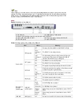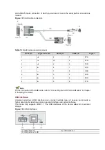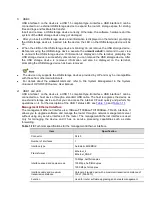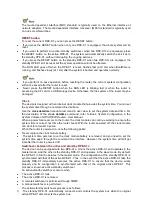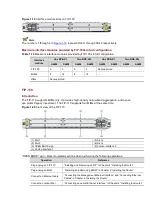
Figure 1-19
Interface module slots on FIP-100
The numbers 1 through 4 in
Figure 1-19
represent Slot 1 through Slot 4 respectively.
Maximum interface modules provided by FIP-100s in full configuration
Table 1-19
Maximum interface modules provided by FIP-100s in full configuration
Interface
module
One RPE-X1
Two RPE-X1s
One RSE-X1
Two RSE-X1s
A6604
A6608
A6604
A6608
A6604
A6608
A6604
A6608
FIP-100
2
4
2
4
Not supported
MIMs
8
16
8
16
—
HIMs
Not supported
FIP-110
Introduction
The FIP-110 supports MIMs only. It provides high-density narrowband aggregation, and hence
can protect legacy investment. The FIP-110 supports four MIMs at the same time.
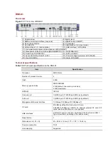
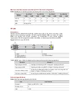
Figure 1-20
Front view of the FIP-110
(1) Slot 1
(2) Slot 2
(3) Slot 3
(4) Slot 4
(5) OPEN BOOK sign
(6) Combo interface 0
(7) Combo interface 1
"OPEN BOOK" sign – Refer to related sections when performing the following operations:
Operation
Reference
Plug/unplug an FIP-110
“Installing and Removing an FIP” in Chapter 4 “Installing the Router”
Plug/unplug an MIM
“Installing and Removing a MIM” in Chapter 4 “Installing the Router”
Connect an Ethernet cable
“Connecting the Management Ethernet Interface” and “Connecting Ethernet
Cables” in Chapter 4 “Installing the Router”
Connect an optical fiber
“Connecting an optical Ethernet interface” in Chapter 4 “Installing the Router”

