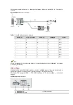
and a DB-25 (male) connector, of which you can select one to the serial
needed.
Figure 1-15
AUX cable connectors
Table 1-15
AUX cable connector pinouts
RJ-45 pin
1
2
3
4
5
—
6
7
8
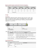
For the connection of the AUX cable, refer to “Connecting the AUX Port to a Modem” in Chapter
4 “Installing the Router”.
USB interfaces
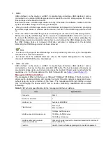
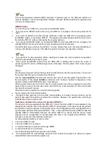
Universal serial bus (USB) interfaces can connect multiple types of devices and provide a
higher data transfer rate than common parallel interfaces and serial interfaces.
The device fully supports USB 1.1. The USB interfaces of the device allow for conven
storage.
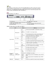
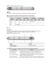
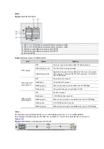
Figure 1-16
USB interfaces
(1) USB interface 0
(3) USB interface 1 LED
25 (male) connector, of which you can select one to the serial port on a modem as
AUX cable connectors
AUX cable connector pinouts
Signal direction
DB-25 pin
DB-9 pin
4
7
20
4
2
3
8
1
—
7
5
3
2
6
6
5
8
For the connection of the AUX cable, refer to “Connecting the AUX Port to a Modem” in Chapter
Universal serial bus (USB) interfaces can connect multiple types of devices and provide a
higher data transfer rate than common parallel interfaces and serial interfaces.
The device fully supports USB 1.1. The USB interfaces of the device allow for conven
(2) USB interface 1
(3) USB interface 1 LED
port on a modem as
9 pin
Signal
RTS
DTR
TXD
DCD
GND
RXD
DSR
CTS
For the connection of the AUX cable, refer to “Connecting the AUX Port to a Modem” in Chapter
Universal serial bus (USB) interfaces can connect multiple types of devices and provide a
higher data transfer rate than common parallel interfaces and serial interfaces.
The device fully supports USB 1.1. The USB interfaces of the device allow for convenient

