horsch LEEB 12 TD Operating Instructions Manual Download Page 67

The pressure filter is equipped with 80 meshes/

inch² insert as standard. Depending on the use, 

additional filter inserts with 50 or 100 meshes/

inch² insert are available.
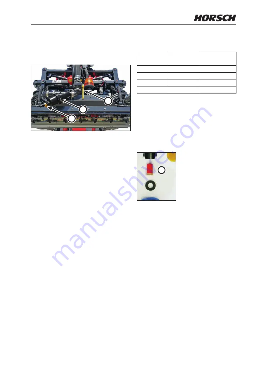
1

3

2

1  

Auxiliary pressure filter

2  

Shut-off lever

3   Valve

Clean  the auxiliary  pressure filter as needed. 

Lower the parallelogram for this purpose. Turn 

the yellow lever to the right (2) by 90° to thus 

block the flow to the pressure filter. Open the 

small yellow valve at the lift (3) and collect any 

draining agent. Dispose of the agent if necessary 

or return it to the spraying mixture container. 

Open the filter housing with the pressure filter 

wrench. Clean the auxiliary pressure filter.

Repeat all steps in the opposite order after 

cleaning.

Dome screen

The dome screen prevents contaminants from 

entering into the spraying mixture container 

during filling through the dome. The screen has 

a standard mesh size of 1 mm.

Drain filter in the tank

The drain filter in the tank prevents settled 

agents from being deposited in the suction fitting.

Suction filter

The  suction  filter  filters  the  water  /  chemical 

before it enters into the centrifugal pump (mesh 

size 0.9 mm).

Overview of pressure filter elements

Meshes/

square inch

Nozzle 

size

Mesh size 

[mm]

32
50

from ‘03’

0.35

80

‘02’

0.20

100

up to ‘015’

0.15

Filter  cleaning,  see  chapter  Cleaning, 

maintenance and repair.

Nozzle filter (optional)

The  nozzle  filter  (a)  prevents  clogging  of  the 

spraying nozzles.

a

Overview of nozzle filters

24 

meshes/square inch

from nozzle size: 

06’ and bigger

Filter area: 

5.00 mm²

Mesh size: 

0.50 mm

50 meshes/square inch 

for nozzle size: 

'02' to '05'

Filter area:  

5.07 mm²

Mesh size:  

0.35 mm

100 meshes/square inch

for nozzle size: 

015’ and smaller

Filter area:  

5.07 mm²

Mesh size: 

0.15 mm

62

63

Summary of Contents for LEEB 12 TD

Page 1: ...TRANSLATION OF THE ORIGINAL OPERATING INSTRUCTIONS READ CAREFULLY PRIOR TO STARTING UP KEEP OPERATING INSTRUCTIONS IN A SAFE PLACE ART ISSUE OPERATING INSTRUCTIONS ART 08 2020 LEEB 12 TD 60015262...

Page 2: ......

Page 3: ...9431 7143 9200 E mail info horsch com Customer No HORSCH Confirmation of receipt of machinery Warranty claims become only effective when the first use of the machine is reported to HORSCH Maschinen G...

Page 4: ...21 Schwandorf _________________________ Theodor Leeb Gesch ftsf hrer Gezogene Pflanzenschutzspritze Leeb 12 TD Translation of EC Declaration of Conformity Directive 2006 42 EC The manufacturer HORSCH...

Page 5: ......

Page 6: ...37 Fluid circuit Construction elements on machines of the CCS Pro variant 38 Two tank system with variant CCS Pro 39 Supply lines between tractor and machine 39 Traffic compliant equipment 40 Instruct...

Page 7: ...ing refill quantities 101 Filling table for residual areas 102 Filling the spraying mixture container through the filling port 104 Direct filling External filling optional 104 Filling via the filling...

Page 8: ...ons for dual line service brake system workshop work 151 Maintenance of axle 151 Checking the bearing play of the wheel hub workshop work 151 Check the wheel hub bearing clearance workshop work 152 Re...

Page 9: ...5...

Page 10: ...nfirmed proper acceptance of the machine The warranty period starts with the date of delivery The operating instructions were prepared based on the EC Machinery Directive EN Standards and German laws...

Page 11: ...model and serial number Purchasing date and operating hours or area performance Type of problem Warranty claim processing Warranty claim forms must be submitted to HORSCH through your local HORSCH sa...

Page 12: ...with The permissible axle and drawbar loads must not be exceeded during road travel Any other kind of use of the machine contradict ing the above especially connecting attachment to an agricultural t...

Page 13: ...h the safe opera tion of the vehicle The person knows all applicable road traffic regulations and is in possession of a valid driving permit for road travel A person being instructed must only work wi...

Page 14: ...to chemicals shoes resistant to chemicals face protection safety goggles to protect against splashes Respirator Provide effective protective equipment in proper condition Never wear rings bracelets o...

Page 15: ...to the undercarriage Consider your personal abilities carriage way traffic sight and weather conditions In addition pay attention to the notes in chapter Commissioning Safety in operation Commissionin...

Page 16: ...ics The hydraulic system is under high pressure Escaping fluid can penetrate the skin and cause serious injuries In the event of injury consult a doctor immediately The machine s hydraulics has severa...

Page 17: ...ate the slope compensation manually What to do in case of voltage flashover Voltage flashover generates high electric volt ages on the outside of the machine This results in extreme voltage difference...

Page 18: ...ma chine for children before driving off and commissioning the machine Ensure sufficient visibility Check the condition of the folding boom and their mounting before use Ensure sufficient stability of...

Page 19: ...the crop protection sprayer Store all relevant information about the crop protection agents used safety data sheets instructions for use etc in the document roll The water quality the water hardness...

Page 20: ...ho has been trained by HORSCH for this purpose Comply with country specific instructions for weights weight distribution and dimensions For equipment influencing the weight or weight distribution the...

Page 21: ...and signs of damage Rem edy any faults immediately Screw connections loosened for the purpose of care and maintenance work must be retighten after work is completed Dispose of oils greases and filters...

Page 22: ...10 m 10 m Danger zone when folding the folding boom 10 m 10 m 10 m 10 m Failing to pay attention to the danger zone can result in severe or even fatal physical injuries Do not stand under lifted loads...

Page 23: ...e starting maintenance and repair work 04002983 Before commissioning the machine you need to read and follow the operating instructions 04002983 No passengers are allowed to ride on the machine 040014...

Page 24: ...substances 04001456 Danger of poisoning no drinking water 04002623 Do not stand in the slewing range of the machine 04002625 Do not stand inside the range of a lifted but unsecured load 04002626 Keep...

Page 25: ...The pressure accumulator is charged with gas or oil pressure Dismantle and repair only in strict compliance with the instructions in the technical manual 00381135 21...

Page 26: ...Position of safety stickers depending on equipment Safety stickers with the addition 2x can be found on either side of the machine 2x 2x 2x 2x Only with PTO shaft pump option 22...

Page 27: ...Safety stickers with the addition 2x can be found on either side of the machine 2x 23...

Page 28: ...the equipment can be transported on public roads either attached to a tractor or on a trailer or low loader The permissible dimensions and weights for transport must be complied with The tractor must...

Page 29: ...to ensure optimal braking behaviour and minimal brake lining wear Initial commissioning of the suspension For the transport on a truck the machine s suspension must be lowered to the transport mode Se...

Page 30: ...completely and secure it with a locking nut Transport position suspension mode Press the button until the dot on the symbol appears in green The transport mode must be left as soon as the crop protec...

Page 31: ...y kg 300 800 Axle load per axle empty kg 3500 4400 max total length in transport position m 9 70 11 70 Transportwidth in transport position m 2 55 3 00 Height m 3 88 3 98 Track widths m 2 00 2 25 Grou...

Page 32: ...uipment Data with tyres IF 520 85 R 42 Machine type 12 TD Technical residual quantities incl pump level ground on request Contour line 15 travel direction to the left on request 15 travel direction to...

Page 33: ...truction EC vehicle type Type plate The type plate with the CE marking is located on the frame of the machine Data on the type plate Dimensions Data in mm transport dimensions 12 TD Folding boom 15 24...

Page 34: ...ay differ from country to country Comply with the national registration regulations Permissible total weight and tyres The permissible total weight of the machine depends on the permissible drawbar lo...

Page 35: ...2 4 4300 2 4 4130 2 4 5510 3 2 5090 3 2 4880 3 2 6280 4 0 5800 4 0 5570 4 0 3 A l l i a n c e 420 95 R50 VF 177 D 4050 1 2 5430 2 0 6330 2 8 6830 3 2 4 M i c h e l i n S p r a y B I B 420 95 R50 VF 17...

Page 36: ...F LI 167 D 3875 1 2 3875 1 2 3875 1 2 4625 1 6 4625 1 6 4625 1 6 5150 2 0 5150 2 0 5150 2 0 5450 2 4 5450 2 4 5450 2 4 14 A l l i a n c e 520 85 R42 IF 169 D 4000 1 2 4000 1 2 4000 1 2 4875 1 6 4875 1...

Page 37: ...ctor engine power 12 TD from 132 kW 180 PS Note These values apply to flat terrain Depending on use conditions e g very steep hilly terrain higher engine power may be required Electrics Battery voltag...

Page 38: ...s 1x dual acting for hydraulic support 1x pressureless return 1x pressure supply for vehicle version with passive follow up steering 1X single acting control unit for locking the follow up axle with h...

Page 39: ...praying mixture container 2 c Filling dome spraying mixture container d External control terminal with Filling level indicator e Slewable illuviation valve f Fresh water tank g Connection of fresh wat...

Page 40: ...y acc to ISO 4406 18 16 13 Always plug in all hydraulic lines Otherwise components may get damaged because of interrelated functions Ensure cleanliness and tight fit of all plug and socket connections...

Page 41: ...Safety and protective features Folding boom rest for inside wing Folding lock Parallelogram lock Slope compensation Railing for working platform 37...

Page 42: ...16 Pressure filter 17 3 way valve pressure output 18 Pressure output 19 Flow meter 20 3 way valve circulation 21 Folding boom 22 Injector 23 Internal cleaning 24 Agitator 25 Switching unit tank 1 out...

Page 43: ...o a certain point and then the front tank 25 is drained to a cer tain point followed again by the rear tank The system guarantees optimal weight distribu tion to ensure sufficient drawbar load on the...

Page 44: ...ant equipment 1 2 1 1 1 1 1 1 2 1 6 spotlights yellow 2 Red white clearance lamp 3 6 5 4 3 Warning board square 4 Tail light turn signal light 5 Identification plate holder with lighting left 6 Wheel...

Page 45: ...7 7 Rotation beacon folding boom middle section optional 8 8 Folding boom headlands lighting optional 9 9 Illuviation centre lighting optional 41...

Page 46: ...lgemein toleranz Horsch Maschinen GmbH nderungen sind untersagt Landwirtschaft aus Leidenschaft HORSCH Maschinen GmbH Sitzenhof 1 92421 Schwandorf www horsch com Tr gerfolie wei Schrift schwarz 003803...

Page 47: ...s worn it must be replaced without delay Hydraulic support The hydraulically operated support supports the uncoupled trailed sprayer Operation takes place via a double acting control valve on the trac...

Page 48: ...e active The switch must be operated by the driver However the spraying pump remains active stirring is possible During road travel the switch must always be set to OFF so that steering is locked Swit...

Page 49: ...trol unit is pressurised Field mode Switch the control unit to floating position Open the shut off valve This allows the trailing steering axle to follow the tractor Road mode At low travel speed the...

Page 50: ...ear axle Under 25 km h The axle is in the follow up mode Above 25 km h The axle is disabled automatically to ensure increased driving stability and safety DANGER Danger of accident caused by the machi...

Page 51: ...mechanical steering end stop so that it is only activated when the electrical steering end stop fails Information on the adjustment of the electronic steering limitation is provided in the terminal o...

Page 52: ...ght must be adapted to the tractor Observe the Commissioning section and associated Terminal operating instructions in this regard Mechanical release mechanism of suspension The undercarriage height c...

Page 53: ...o the bracket Parking brake Actuating button to release the pneumatic brake When uncoupling the machine from the tractor the pneumatic brake of the sprayer automatically engages in the brake position...

Page 54: ...nt must match the value given on the ALB plate The ALB type plate is located on the frame of the right machine side under the covering Input pressure 6 5 bar The plate shows the setting data according...

Page 55: ...achine may otherwise start rolling off with the tractor 1 Engage the brake of the tractor 2 Open the lid of the coupling head on the tractor 3 Fasten the coupling head of the brake line yellow correct...

Page 56: ...l automatically switch over and operate the service brake system in dependence on the automatic load dependent brake pressure regulator Spraying mixture container WARNING Danger of poisoning Do not cl...

Page 57: ...the field cleaning the suction fitting as well as the spraying lines with the tank filled Cleaning with 1 2 hose with hose reel and washing gun optional Cleaning with high pressure cleaner optional 1...

Page 58: ...ring loaded indexing bolt and fold down the access ladder with the other hand Fold up the ladder after use and especially before transport travel until the spring loaded indexing bolt engages WARNING...

Page 59: ...ing dome Dome screen Hand washing tank NOTE Fill only clean water into the hand washing tank WARNING Danger or poisoning by contaminated water in the hand washing tank Never use the water in the hand...

Page 60: ...as dry running protection and for cooling Check the pressure on the pressure gauge 3 of the compensation tank The compensation tank is located at the left side of the machine next to the illuviation v...

Page 61: ...to check or top up the oil level Contact HORSCH Service if the oil must be topped up daily or if the oil is discoloured Technical data Type AR 185 Flow rate in l min at 480 rpm 100 max flow rate in l...

Page 62: ...tivate deactivate the canister flushing 10 Activate deactivate the shock nozzle only with illuviation valve from stainless steel rinsing nozzle in the lower area 11 Activate deactivate closed circuit...

Page 63: ...hed to the housing of the illuviation valve to facilitate filling Bags with crop protection agent can be put down here Illuviation valve tray with stainless steel funnel Washing gun A washing gun for...

Page 64: ...cleaning system two optional variants are available 1 2 hose with hose reel and washing gun CCS Continuous inside cleaning Continuous cleaning system NOTE Fast cleaning process of the sprayer without...

Page 65: ...t on the external control terminal on the main terminal The agitator can also be switched off completely in order to minimize the residual quantity inside the spraying mixture containers At the highes...

Page 66: ...mesh sizes The mesh sizes of self cleaning pressure filters and nozzle filters optional must always be smaller than the nozzle opening of the nozzles used Please note that the use of pressure filter e...

Page 67: ...ants from entering into the spraying mixture container during filling through the dome The screen has a standard mesh size of 1 mm Drain filter in the tank The drain filter in the tank prevents settle...

Page 68: ...uction connection for spraying mixture container filling 4 Filling port for fresh water tank 5 Spraying mixture tank residue drain 6 Spraying mixture tank pressure output Main control terminal Sprayin...

Page 69: ...be followed Multi function handle The multi function handle is an ISOBUS capable operating element and can additionally be connected to the terminal to ease operation It contains the functions most fr...

Page 70: ...ON OFF m Sections ACTIVATION from left n Sections ACTIVATION from right o Sections DEACTIVATION from left p Sections DEACTIVATION from right q Spraying quantity REDUCTION by 5 r Spraying quantity INCR...

Page 71: ...ant WARNING To avoid contamination of the tractor cabin it must not be entered with used protective clothing Protective clothing shall always be stored in the transport and safety container provided f...

Page 72: ...s The machine can be fastened at the following points to secure it for transportation Both sides at the front of the machine Both sides at the rear of the machine NOTE The chapter Safety notes must be...

Page 73: ...am lock 8 Slope compensation 9 Folding boom rest WARNING Danger of crushing and impact for persons when lifting or lowering for height adjust ment of the spraying boom Instruct persons to leave the da...

Page 74: ...ng boom Folding boom 5 piece with reduced working width 15 m 15 m 24 30 m Folding boom 5 piece with reduced working width 18 m 18 m 30 36 m Folding boom 7 piece with reduced working width 12 m and 21...

Page 75: ...ding boom 7 piece with reduced working width 24 m 24 m 30 36 m Folding boom 7 piece with reduced working width 27 28 m 27 28 m 38 42 m Folding boom 7 piece with reduced working width 30 m 30 m 44 45 m...

Page 76: ...rfaces such as e g water puddles the ultrasonic signal may be reflected The control must in these areas be deactivated BoomControl does not relieve the driver from his responsibility to constantly che...

Page 77: ...n of the folding boom via middle section height guidance and independent bending of both folding boom halves controlled by 4 sensors distributed over the entire folding boom Transport lock WARNING The...

Page 78: ...boom put down Parallelogram lock The stroke of the parallelogram must always be locked during road travel The parallelogram is locked automatically as soon as the folded folding boom is in the end pos...

Page 79: ...tion unlocked Slope compensation locked Uniform transverse distribution is only achieved with the slope compensation unlocked NOTE Before starting road travel make sure that the folding boom is locked...

Page 80: ...vidual sections or the entire spraying line for the first time the biocatalytic solution is directly and well mixed available This circulation successfully prevents the formation of deposits and block...

Page 81: ...e type is used Only the vertically arranged nozzle will be supplied By turning the nozzle body another nozzle is brought into use In intermediate positions the nozzle body is switched off NOTE Flush t...

Page 82: ...nged clamp Multiple nozzle body manual 4 fold The 4 fold nozzle body is recommended if more than only one nozzle type is used Only the two vertical nozzles will be supplied They can be activated indiv...

Page 83: ...and install them Use the delivered tool for this purpose Nozzle cleaning Clean the nozzles if required Do not damage nozzles and nozzle filters when cleaning CAUTION CAUTION Spraying mixture running o...

Page 84: ...mix mineral oils with bio oils Observe the maximum permissible hydraulic oil pressure of 200 bar Only connect clean hydraulic couplings Insert the hydraulic plugs into the hydraulic sockets until the...

Page 85: ...shaft speed of the tractor complies with the permissible speed of the device max permissible speed 750 rpm Check all screw connections in regular intervals DANGER Danger of injuring during assembly B...

Page 86: ...r must be shut down and the compressor depressurized The pressure gauge should not indicate any pressure Keep a safe distance to hot surfaces Check the intake filter daily for contamination Clean as r...

Page 87: ...7 8 9 7 Filler neck with oil dipstick min max 8 Drain plug 9 Electronic pressure switch with ON OFF switch Technical data max air flow rate l min 450 max air pressure bar 8 Air volume in frame tube l...

Page 88: ...kage repair if necessary workshop work Air pressure too low Electronic pressure switch defective or incorrectly adjusted Check and repair or replace if necessary workshop work Suction filter blocked C...

Page 89: ...ceive GPS signals but the differential signal is absent Accuracy is therefore very low Green The GPS receiver receives GPS signals and differential signals Installation CAUTION Risk of crushing from v...

Page 90: ...ages to the terminal may occur from a short circuit Switch off the terminal before connecting the connecting cable of the GPS receiver to it 1 Switch off the terminal 2 Route the connecting cable of t...

Page 91: ...injuries NOTE Information on the configuration of the camera is provided in the associated terminal operating instructions Wind meter optional A wind meter can be mounted on the top side of the sprayi...

Page 92: ...inal All main and auxiliary nozzles remain in use Border nozzle If an edge nozzle is activated via the terminal with 1 fold nozzle bodies level 1 of the first or last main nozzle is switched off with...

Page 93: ...e enabled If the main switch 4 is deactivated all active sections or border edge nozzles are in the preselected state Regarding the allocation of the respective sections or border edge nozzles to the...

Page 94: ...cle the pump 3 is activated for approx 4 seconds and delivers approx 0 4 litres of fresh water with 2 5 bar to the cleaning nozzle 1 3 Filter NightLight cleaning 2 The filter is located below the fres...

Page 95: ...ertaining terminal operating instructions NOTE The maximum settings on the compressed air controller of the control valve must not be ch anged Danger of tyre exploding Settings may only be made by the...

Page 96: ...mpty Drain them if necessary Drain the air vessels daily Pack storage optional An optional pack storage can be installed at the right machine side under the covering This is provided for the secure tr...

Page 97: ...s Connecting Parking DANGER There is a risk that persons may become crushed and severely injured between machine and tractor Instruct persons to leave the area between tractor and machine No person mu...

Page 98: ...them Machines with ball and socket coupling Lower the drawbar or spherical cap with the hydraulic support onto the ball Position the hold down Check the gap between hold down and spherical cap and adj...

Page 99: ...e bolt must be inserted and secured on the left side of the steering drawbar to lock the steering mechanically the proper connection of the supply lines the lighting system for damage function and cle...

Page 100: ...the holder 6 Unplug the brake lines ISOBUS and lighting and hook in the bracket Attach the covering caps 7 Depressurise the hydraulic lines and disconnect them 8 Unhitch the machine Machines with draw...

Page 101: ...efore fold ing that no persons are present in the danger zone Comply with the accident prevention instruc tions CAUTION Damages to the machine and the supporting surface Fold the machine only on a lev...

Page 102: ...iaphragm valve at regular intervals to prevent subsequent dripping of the nozzles Refer to the section Nozzle assembly and cleaning NOTE The folding process must be performed while the machine is at s...

Page 103: ...filters must always be smaller than the nozzle opening of the nozzles used Notes given by the manufacturer of the crop protection agent must be followed The standard pressure filter element used in th...

Page 104: ...er persons Protect contaminated crop protection agent canisters and the contaminated crop protection sprayer against precipitation Ensure sufficient cleanliness during and after spraying mixture prepa...

Page 105: ...Calculation formula and solution Component quantity ha x area ha required quantity l or kg Water 400 l ha x 2 5 ha 1000 l Product A 1 5 kg ha x 2 5 ha 3 75 kg Product B 1 0 l ha x 2 5 ha 2 5 l Example...

Page 106: ...1 12 13 13 14 15 16 16 17 18 18 50 12 14 14 15 16 17 18 19 20 20 21 22 23 60 14 16 17 18 19 20 22 23 23 24 25 26 27 70 17 19 20 21 22 23 25 27 27 28 29 31 32 80 19 22 22 24 26 26 29 30 31 32 34 35 36...

Page 107: ...issible payload of the crop protection sprayer when filling the spraying mixture container Pay attention to the specific weight of the fluid to be filled in When filling keep an eye on the level gauge...

Page 108: ...4 Start the filling process via the external control terminal 5 The suction fitting switches off automatically when the desired filling level is reached The filling process can be aborted at any time...

Page 109: ...using a water line with free outflow 4 Always keep an eye on the level gauge on the terminal while filling 5 Stop filling the spraying mixture container at the latest when the filling limit is reache...

Page 110: ...Illuviation valve DANGER Wear appropriate protective clothing for the illuviation flush in the preparations Observe the regulations and notes as well as the safety data sheet of the crop protection a...

Page 111: ...process on machines of the CCS Pro variant 1 Enter the desired container content in the terminal 2 Connect the suction hose to the filling connection Filling connection 3 Start filling via terminal 4...

Page 112: ...c d e 1 Open the lid on the illuviation valve 2 Switch on the illuviation valve on the terminal 3 Fill the required preparation quantity as calculated for filling the tank into the illuviation valve...

Page 113: ...lve e again 10 Switch off the illuviation valve on the terminal again 11 Top up the water shortfall 12 Adjust the desired agitator power Pre cleaning the canister with spraying mixture a b c d e 1 Ope...

Page 114: ...before preparing the next spraying mixture container filling or when diluting the residual quantity for the last spraying mixture container filling Spraying operation Special notes for spraying opera...

Page 115: ...interruptions of spraying operation it is mandatory to clean filters pump fitting and spraying lines Folding boom control WARNING Danger of crushing and impact for persons staying in the danger zone w...

Page 116: ...6 bar max Spraying 1 Switch on the terminal 2 Adjust the agitator 3 Prepare the spraying mixture as specified by the crop protection agent manufacturer and stir it up 4 Unfold the spraying boom 5 Set...

Page 117: ...ance instructions for the corresponding crop protection agent Spraying with 25 cm nozzle spacing and reduced target area distance The risk of windward drifting can be considerably reduced by reducing...

Page 118: ...tion on the terminal Control screen terminal circulation 4 After drainage switch off the circulation to shut off the pump 5 Close the ball valve a and remove the discharge hose 6 Close the pressure ou...

Page 119: ...ne Irregular fluid flow from the pump Check valves on suction and pressure side replace if necessary Therequiredandentered application quantity is not reached High travel speed low pump drive speed Cl...

Page 120: ...individual nozzle output for volu metric measurement of the crop protection sprayer Procedure The tables apply to 50 cm nozzle spacing Nozzle sizes and colour coding acc to ISO 10625 With diagram and...

Page 121: ...Diagram a with example 117...

Page 122: ...lication quantity l ha Nozzle output l min Nozzle size Universal table b with 50 cm nozzle spacing with example The values apply for water of 20 C pressure measured directly at the nozzle Check the va...

Page 123: ...for the line s with the required placing quantity use approximate values if necessary 4 Read nozzle size pressure and nozzle output Example 1 Placing quantity Travel speed 200 l ha 8 km h 2 See placin...

Page 124: ...Colour Type Colour Pres sure bar Pres sure bar l min l min Placing quantity in l ha at km h Placing quantity in l ha at km h Universal table with 50 cm nozzle spacing with example The values apply fo...

Page 125: ...XRC nozzles 015 1 1 5 LU XRC nozzles 02 1 2 5 LU XRC nozzles 03 1 3 0 LU XRC nozzles 04 08 1 5 0 AD DG TT all sizes 1 5 6 AI all sizes 2 8 ID all sizes 2 8 Air Mix nozzles all sizes 1 6 IDK IDKN all...

Page 126: ...ying line The re sidual quantity in the spraying line depends on the working width of the folding boom Once the residual quantity in the spraying mixture container has reached a level of just 100 litr...

Page 127: ...treated residual area 4 Repeat steps 2 and 3 for a second if necessary a third time Diluting the residual quantity with machines of the variant CCS Pro 1 Call up the cleaning menu on the main control...

Page 128: ...rop protection sprayer after cleaning especially after cleaning with a high pressure cleaner steam jet or when using grease dissolving cleaning agents Pay attention to the statutory regulations concer...

Page 129: ...t the spraying nozzles in place CCS Continuous inside cleaning Continuous Cleaning System Continuous inside cleaning is only possible with machines of the CCS and CCS Pro variants The complete cleanin...

Page 130: ...ential is too high Pressure filter 1 Switch off the folding boom circulation 2 Close the ball valve for pressure output 3 Drain the filter Open the valve for this purpose 4 Unscrew the filter 5 Cleani...

Page 131: ...he tank empty NOTE The initially placed residual quantity is undi luted Therefore place the residual quantity on an untreated surface Cleanthesprayingmixturecontainerafteruse Main cleaning on machines...

Page 132: ...n and pressure filters NOTE In multiple nozzle systems all existing nozzles must be opened for cleaning There is danger of deposits if this instruction is not followed Cleaning the sprayer with the ta...

Page 133: ...e agitator internal cleaning injector and spraying pump as well 3 Call up the cleaning menu on the terminal 4 Select the Air Valve function in the submenu 5 Start the program 6 The blow out process en...

Page 134: ...Follow the road traffic regulations of the respective country Wheel swapping NOTE Perform wheel swapping only per axle Danger of machine toppling over 1 Follow the Changing wheels section 2 Lift both...

Page 135: ...Contamination with crop protection agents Only carry out all maintenance work on the crop protection sprayer after it has been cleaned NOTE Regular and proper maintenance will keep the crop protection...

Page 136: ...es Thoroughly clean the crop protection sprayer before each repair or maintenance espe cially the parts contaminated by the spraying mixture Carry out repairs only on machines shut down and secured ag...

Page 137: ...icating so that no dirt is pressed into the bearings Press the contami nated grease completely out of the bearings and replace it with fresh grease Lubricants NOTE A lithium saponified multi purpose g...

Page 138: ...s of the hydraulic system and water system In use Hydraulics WARNING Lock all hydraulically operated parts before any work on the hydraulic system Depressurise the hydraulics on the tractor and implem...

Page 139: ...me screen Line filters in the nozzle lines Spraying nozzles Centrifugal pump Piston diaphragm pump check for leaks daily Centrifugal pump check for leaks daily Hose assembly check for leaks 50 h Line...

Page 140: ...oward the direction of travel Direction of travel Ball OK ball worn 40 h Before connecting Direction of travel Spherical cap OK spherical cap worn 40 h Note possibly existing wear limits on the hold d...

Page 141: ...tting yearly Wheels brakes Undercarriage wheels Check for damage cracks etc daily Check fastening retighten wheel nuts see above see above Check air pressure daily Bearing of wheel hub Check clearance...

Page 142: ...50 h At the end of the season Complete machine Perform care and cleaning work do not spray plastic parts with oil or similar Spray the piston rods of the hydraulic cylinder with a suitable corrosion p...

Page 143: ...dditives must be used for lubrication tasks Use only cleaned hydraulic oil that complies with the demanded cleanliness class Cleanliness class 9 as per NAS 1638 Cleanliness class 18 16 13 as per ISO 4...

Page 144: ...e wing outside wing lubricate 7 on both sides 50 h Middle section inside wing lubricate 5 on both sides 50 h Folding boom 5 piece 2 fold folding with chain Outside wing collision protection lubricate...

Page 145: ...Overview of lubrication points basic machine Hydraulic support Parking brake Steering axle Brake lever Ball socket PTO shaft pump 141...

Page 146: ...Suspension cylinder Suspension cylinder 142...

Page 147: ...nection for folding booms over 30 m standard for folding booms under 30 m optional Middle frame central frame connection for folding booms under 30 m Pendulum frame for folding booms over 30 m standar...

Page 148: ...Parallelogram lock Pendulum lock cylinder Parallelogram Parallelogram 144...

Page 149: ...Overview of folding boom lubrication points Folding boom 5 piece 2 fold folding Outside wing collision protection Middle section inside wing Inside wing outside wing 145...

Page 150: ...of the folding boom control The BoomControl ProPlus comes with three additional lubrication points Folding boom 5 piece with chain only with BoomControl ProPlus Outside wing collision protection Midd...

Page 151: ...trol The BoomControl ProPlus comes with three additional lubrication points Folding boom 7 piece 2 fold folding with coupling bar only with BoomControl ProPlus Outside wing collision protection Middle...

Page 152: ...boom control The BoomControl ProPlus comes with three additional lubrication points Folding boom 7 piece triple folding only with BoomControl ProPlus Outside wing collision protection Middle section...

Page 153: ...this Pipe hose lines and coupling heads must not show any external damage or corrosion Joints e g on fork heads must be properly secured light moving and should not be worn Ropes and actuating cables...

Page 154: ...checked continuously and adjusted if this should be necessary Resetting the brake is necessary if approx 2 3 of the max cylinder stroke is utilized for flat out braking Adjustment work must be carried...

Page 155: ...l hub workshop work WARNING Danger of crushing shearing cutting cutting off being caught wound up pulled in caught and knocked by accidental starting and rolling away of the tractor machine combinatio...

Page 156: ...the wheel hub bearing WARNING Danger of crushing shearing cutting cutting off being caught wound up pulled in caught and knocked by accidental starting rolling away of the tractor machine combination...

Page 157: ...hub and axle nut again 14 Adjust the bearing and brake settings 15 Perform a function check and corresponding test drive after the adjustment Correct any detected deficiencies immediately NOTE For lub...

Page 158: ...chine combination Secure both tractor and crop protection sprayer against accidental starting and unintended rolling before you start working on the machine 500 500 VL VR HL HR VL VR HL HR 500 500 Rig...

Page 159: ...e bled This is done by selecting all hydraulic functions several times Hydraulic cylinders must extend and retract without jerking Danger zones must be blocked off during commissioning When performing...

Page 160: ...seals foreign objects loose hose clamps Assembly and disassembly of hydraulic hoses NOTE Use only original spare hoses from HORSCH LEEB AS These spare hoses withstand the chemical mechanical and ther...

Page 161: ...can be calculated Distance travel speed x spraying duration Multiplied with the working width gives you the area that would be processed when working with the simulated travel speed and spraying time...

Page 162: ...00 l 1 850 l Correction factor 0 973 The placed quantity is too high the value under parameter 457 therefore needs to be corrected New value pulses 100 l 2 100 x 0 973 2 043 Wheels and tyres Check the...

Page 163: ...the jack lifting point of the axle The jack lifting points are listed in the chapter Safety stickers and marked on the machine with the following stickers 00385757 4 When using a hydraulic jack witho...

Page 164: ...y specified hydraulic oil Change the oil and filter every 1200 h or annually Do not fill in too much oil the oil level must not be higher than half the sight glass Inspection of the crop protection sp...

Page 165: ...ed hose on the flow meter 3 Connect the two other ends of the hoses of the test adapter set to the test device 4 To perform the test circulation must be acti vated on the terminal 5 Deactivate circula...

Page 166: ...not subjected to lubrication slightly with oil NOTE Make a note of all service and maintenance work that has to be done before the start of the next season and place a corresponding order with your H...

Page 167: ...pressure filter Drain fluid from the compressed air vessel Empty the hand washing tank Open the drain plug on the bottom of the tank for this purpose and then close it again Hand washing tank drain p...

Page 168: ...er residue drain and pressure output again Put on the cap again for pressure output direct filling filling the fresh water tank suction connection for filling the spraying mixture container and residu...

Page 169: ...ntifreeze mix is present in the sprayer Machines of the CCS Pro variant Let the existing cleaning programs run through several times with fresh water Completely lubricate the machine as per lubricatio...

Page 170: ...nance which must be disposed of appropriately For the waste disposal of auxiliary and operat ing media as well as other chemicals you must strictly comply with the specifications in the respective saf...

Page 171: ...6 1 8 9 10 4 6 1 00 5 5 6 8 10 4 15 3 17 9 7 1 00 9 3 11 5 17 2 25 30 8 1 25 13 6 16 8 25 37 44 8 1 00 14 5 18 27 40 47 10 1 50 26 6 33 50 73 86 10 1 25 28 35 53 78 91 12 1 75 46 56 86 127 148 12 1 25...

Page 172: ...5 9 95 0 108 5 149 1 169 5 216 0 244 0 3 4 19 1 169 5 189 8 271 1 298 3 380 0 427 0 7 8 22 2 176 3 196 6 433 9 474 5 610 0 678 0 1 25 4 257 6 278 0 650 8 718 6 915 2 1017 1 1 8 28 6 359 3 406 8 813 5...

Page 173: ...lower spraying pressure Placing quantity too low increase spraying pressure Nozzle selection and control The fluid level which indicates the placing quantity in l ha on one side of the HORSCH Leeb met...

Page 174: ...t nozzles for the application of liquid fertiliser is beneficial if the liquid fertiliser is to enter into the plant through the roots rather than through the leaf The nozzle orifice integrated in the...

Page 175: ...0 72 200 0 257 2 74 204 9 264 2 76 211 6 271 8 78 216 5 278 3 80 222 1 285 8 82 227 9 292 8 84 233 3 300 0 86 233 3 307 5 88 242 2 314 1 90 250 0 321 7 92 255 7 328 3 94 261 2 335 8 96 266 7 342 7 98...

Page 176: ...ide 109 Care 16 CCS Continuous inside cleaning 125 Central control 28 Centrifugal pump 28 56 Spraying pump Circulation system 76 Cleaning 125 Cleaning emptied container 127 Cleaning nozzles 79 Cleanin...

Page 177: ...124 Hillside location 47 Hinged clamp 78 Hitching and uncoupling 12 Hitch ring 43 Hose clamps 131 Hose reel 61 Hoses 52 80 155 Hydraulic connections 80 Hydraulic hoses 80 Hydraulic oil 34 Hydraulics...

Page 178: ...apacity test 160 Putting into storage 162 Putting the sprayer system into winter storage 163 R Rated volume 27 Recycling 166 Refill quantity 100 101 102 Residual area 102 Residual quantity 28 122 Resi...

Page 179: ...95 99 Tractor change 93 Tractor equipment 33 Traffic 10 Road traffic Trailing control 47 Transport 24 Transport lock 73 Transport width 10 27 Travel speed 110 116 119 Twin line brake system 34 50 51 5...

Page 180: ......

Page 181: ...tions and pictograms are approximate and for information only Subject to technical product revisions HORSCH LEEB Application Systems GmbH Kleegartenstra e 54 94405 Landau a d Isar Tel 49 9951 6041 0 F...

Reviews: