


10 - 3
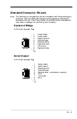
Standard Connector Pinouts
Note: The following pin assignments are not compatible with Honeywell legacy
products. Use of a cable with improper pin assignments may lead to
damage to the unit. Use of any cables not provided by the manufacturer
may result in damage not covered by your warranty.
Keyboard Wedge
10 Pin RJ41 Modular Plug
Serial Output
10 Pin RJ41 Modular Plug
1
Cable shield
2
Cable select
3
Supply ground
4
Terminal data
5
Terminal clock
6
Keyboard clock
7
+5V power
8
Keyboard data
9
10
1
Cable shield
2
Cable select
3
Supply ground
4
Transmit data
5
Receive data - serial data to scanner
6
CTS
7
+5V power
8
RTS
9
10
Summary of Contents for Voyager 1400g Series
Page 1: ... Voyager 1400g Series Area Imaging Scanner User s Guide ...
Page 8: ......
Page 16: ...viii ...
Page 24: ...1 8 ...
Page 50: ...2 26 ...
Page 66: ...3 16 ...
Page 144: ...6 64 ...
Page 148: ...7 4 ...
Page 186: ...9 34 ...
Page 194: ...11 4 ...
Page 210: ...A 14 ...
Page 214: ...Programming Chart 1 0 2 3 6 7 5 4 8 9 ...
Page 216: ...VG1400 UG Rev C 9 14 Honeywell Scanning Mobility 9680 Old Bailes Road Fort Mill SC 29707 ...