Installation and Connections
24
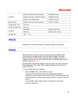
c. For signal wires that are too long, 120
Ω
should be connected parallel
between A, B lines on the far end to reduce reflection and guarantee
signal quality.
d “485 A, B” of DVR cannot connect parallel with “485 port” of other
device.
e. The voltage between of A,B lines of the decoder should be less than
5v.
2. Connect the other end of the cable to the proper pins in the connector
on the camera.
3. Please follow the instructions to configure a camera to enable each
PTZ device on the DVR.
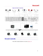
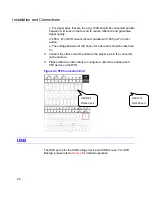
Figure 3-3 PTZ Connection Port
HSVR-16
RS-485 port
HSVR-04
RS-485 port
USB
The USB port is for the USB storage device and USB mouse. For USB
Backup, please refer to
Backup
for detailed operation.
Summary of Contents for HSVR-04
Page 2: ......
Page 47: ...Honeywell 39 Figure 4 14 Motion Detection Zone Setting Figure 4 15 PTZ Activation Setting ...
Page 100: ...Understanding of Menu Operations and Controls 92 Figure 5 38 The Shutdown Menu ...
Page 103: ...Honeywell 95 Figure 6 2 The Internet Options Window ...
Page 133: ...Honeywell 125 Figure 6 39 The Detection Setup Menu Figure 6 40 The Detection Zone Setup ...


